Subaru Legacy (2005 year). Service manual — part 332
EN(H4DOTC)(diag)-97
ENGINE (DIAGNOSTICS)
Diagnostic Procedure with Diagnostic Trouble Code (DTC)
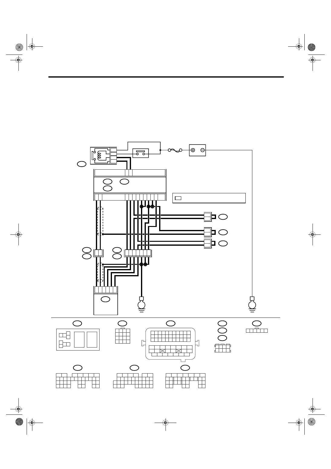
N: DTC P0123 THROTTLE/PEDAL POSITION SENSOR/SWITCH “A” CIRCUIT
HIGH
DTC DETECTING CONDITION:
Immediately at fault recognition
TROUBLE SYMPTOM:
• Erroneous idling
• Engine stalls.
• Poor driving performance
WIRING DIAGRAM:
EN-03524
SBF-7
B135
B:
B137
B136
D:
B362
B84
B138
B122
E1
B20
E57
C:
B135
B362
B20
B21
E57
B84
B122
B138
B137
B136
E
E
D6
B35
16
15
*
*
*
*
7
3
E2
B21
39
38
19
20
35
36
37
4
6
1
2
3
5
D4
D5
C35
C16
B1
B4
D1
D2
D3
C29
C18
5
8
7
6
1 2 3 4
5 6 7 8
9 10 11 12
13 14 15 16
1 2
7 8
3
4
5
6
1 2 3 4 5 6 7 8 9 10 11
12 13 14 15 16 17 18 19 20 21 22
23 24 25
34 35
36 37 38 39 40 41
48 49
50 51 52 53 54
42 43
44 45
46 47
26 27 28 29 30 31 32 33
1 2 3 4
5 6 7 8
1 2 3 4 5 6
1
2
7
8 9
5
6
3
4
10 11 12
19 20 21
29
30 31
13 14 15 16 17
27
28
18
22 23
24 25
26
1
2
7
8 9
5
6
3
4
10 11 12
19
20 21
29 30 31
13 14 15 16 17
27
28
18
22 23
24 25
26
32 33
34 35
1
2
8 9
5
6
3
4
10 11 12
19 20 21
29 30
31
13 14 15 16
17
27
28
18
22 23 24 25 26
7
32 33 34 35
B:
D:
C:
ECM
BATTERY
MAIN RELAY
ELECTRONIC
THROTTLE
CONTROL RELAY
ELECTRONIC
THROTTLE
CONTROL
*
: TERMINAL No. RANDOM ARRANGEMENT

EN(H4DOTC)(diag)-98
ENGINE (DIAGNOSTICS)
Diagnostic Procedure with Diagnostic Trouble Code (DTC)
Step
Check
Yes
No
1
CHECK SENSOR OUTPUT.
1) Turn the ignition switch to ON.
2) Read the data of main throttle sensor signal
using Subaru Select Monitor.
NOTE:
• Subaru Select Monitor
For detailed operation procedure, refer to
“READ CURRENT DATA FOR ENGINE”. <Ref.
to EN(H4DOTC)(diag)-24, Subaru Select Mon-
itor.>
Is the voltage less than 4.63
V?
2
CHECK POOR CONTACT.
Check poor contact in connector between
ECM and electronic throttle control.
Is there poor contact in con-
nector between ECM and elec-
tronic throttle control?
Repair the poor
contact.
Temporary poor
contact occurred,
but it is normal at
present.
3
CHECK HARNESS BETWEEN ECM AND
ELECTRONIC THROTTLE CONTROL.
1) Turn the ignition switch to OFF.
2) Disconnect the connector from ECM.
3) Disconnect the connectors from electronic
throttle control.
4) Measure the resistance between ECM con-
nector and electronic throttle control connector.
Connector & terminal
(B136) No. 18 — (E57) No. 6:
(B136) No. 35 — (E57) No. 3:
Is the resistance less than 1
Ω?
Repair the open
circuit of harness
connector.
4
CHECK HARNESS BETWEEN ECM AND
ELECTRONIC THROTTLE CONTROL.
1) Turn the ignition switch to ON.
2) Measure the voltage between electronic
throttle control connector and engine ground.
Connector & terminal
(E57) No. 6 (+) — Engine ground (
−
):
3) Check the voltage change by shaking the
harness and connector of ECM, and engine
harness connector, while monitoring the value
with voltage meter.
Is the voltage less than 10 V?
Repair the battery
short circuit of har-
ness between
ECM connector
and electronic
throttle control
connector.
5
CHECK HARNESS BETWEEN ECM AND
ELECTRONIC THROTTLE CONTROL.
1) Turn the ignition switch to OFF.
2) Disconnect the connector from ECM.
3) Measure the resistance between ECM con-
nectors.
Connector & terminal
(B136) No. 18 — (B136) No. 16:
Is the resistance more than 1
M
Ω?
Repair the poor
contact in harness.
Replace the elec-
tronic throttle con-
trol.
Repair the short
circuit to sensor
power supply.
EN(H4DOTC)(diag)-99
ENGINE (DIAGNOSTICS)
Diagnostic Procedure with Diagnostic Trouble Code (DTC)
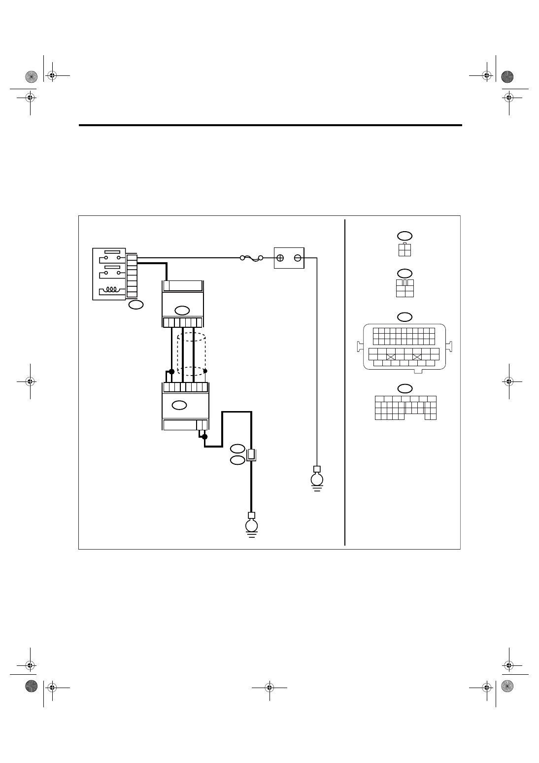
O: DTC P0131 O2 SENSOR CIRCUIT LOW VOLTAGE (BANK 1 SENSOR 1)
DTC DETECTING CONDITION:
Immediately at fault recognition
CAUTION:
After repair or replacement of faulty parts, perform Clear Memory Mode <Ref. to EN(H4DOTC)(diag)-
37, OPERATION, Clear Memory Mode.> and Inspection Mode <Ref. to EN(H4DOTC)(diag)-30, PROCE-
DURE, Inspection Mode.>.
WIRING DIAGRAM:
EN-03522
SBF-5
B47
1
2
4
6
3
5
E
E
B21
F2
54
A6
A7
A2
A3
A26
A33
A25
ECM
B134
3
1
4
2
B18
3 4
1 2
3
4
1
2
5
6
B21
B47
B18
B134
5
6
7
8
2
1
9
4
3
10
24
22 23
25
11 12 13 14 15
26 27
28
16 17
18 19 20 21
33 34
29
32
30 31
MAIN RELAY
FRONT OXYGEN
(A/F) SENSOR
BATTERY
A:
1 2 3 4
12 13 14 15
5 6 7 8
16 17 18 19
9 10 11
20 21 22
23 24 25 26 27 28 29 30 31 32 33
35
34
37
36
39
38
41
40
43
42
44
45
47
46
49
48
51
50
53
52
54
A:

EN(H4DOTC)(diag)-100
ENGINE (DIAGNOSTICS)
Diagnostic Procedure with Diagnostic Trouble Code (DTC)
Step
Check
Yes
No
1
CHECK HARNESS BETWEEN ECM AND
FRONT OXYGEN (A/F) SENSOR CONNEC-
TOR.
1) Turn the ignition switch to OFF.
2) Disconnect the connector from ECM and
front oxygen (A/F) sensor connector.
3) Measure the resistance of harness
between ECM connector and chassis ground.
Connector & terminal
(B134) No. 26 — Chassis ground:
(B134) No. 33 — Chassis ground:
Is the resistance more than 1
M
Ω?
Repair the ground
short circuit of har-
ness between
ECM and front
oxygen (A/F) sen-
sor connector.
2
CHECK HARNESS BETWEEN ECM AND
FRONT OXYGEN (A/F) SENSOR CONNEC-
TOR.
Measure the resistance of harness between
ECM connectors.
Connector & terminal
(B134) No. 26 — (B134) No. 33:
Is the resistance more than 1
M
Ω?
Replace the front
oxygen (A/F) sen-
sor. <Ref. to
FU(H4DOTC)-32,
Front Oxygen (A/
F) Sensor.>
Repair the har-
ness short of har-
ness between
ECM and front
oxygen (A/F) sen-
sor connector.
Нет комментариевНе стесняйтесь поделиться с нами вашим ценным мнением.
Текст