Subaru Legacy (2005 year). Service manual — part 553
4AT(diag)-49
AUTOMATIC TRANSMISSION (DIAGNOSTICS)
Diagnostic Procedure with Diagnostic Trouble Code (DTC)
E: DTC P0719 TORQUE CONVERTER/BRAKE SWITCH “B” CIRCUIT LOW
DTC DETECTING CONDITION:
Brake switch malfunction, open input signal circuit
TROUBLE SYMPTOM:
• Gear is not shifted down when driving a down hill.
• The neutralizing control does not operate.
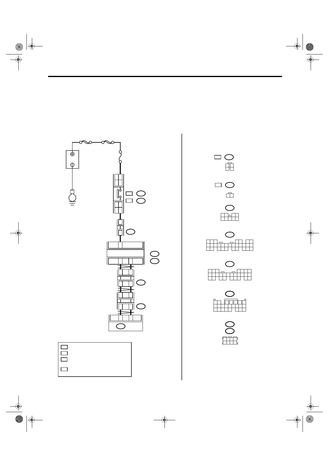
WIRING DIAGRAM:
• LHD model
AT-03158
B159
2
1
3 4
8 9
7
6
5
B280
8
7
6
5
4
3
2
1
22
23
21
20
19
16
15
14
13
12
11
10
9
17
30
18
29
28
27
26
25
24
B281
8
7
6
5
4
3
2
1
21
22
20
19
16
15
14
13
12
11
10
9
17 18
28
27
26
25
24
23
B64
2
1
B54
8
3
4
5
6
7
2
1
18 19 20
17
16
15
14
13
12
11
10
9
24
23
22
21
C:
B:
B159
B280
B:
B281
C:
C23
B20
B30
3
5
9
MAIN SBF
SBF-2
No.8
E
B
A
TTER
Y
STOP LIGHT
SWITCH
JOINT
CONNECTOR
BODY INTEGRATED
MODULE
3
12
TCM
B54
2
4
5
7
B352
JOINT
CONNECTOR
B355
JOINT
CONNECTOR
2
WC
WC
1
OC
2
OC
: WITHOUT CRUISE CONTROL
: WITH CRUISE CONTROL
OC
WC
OC
WC
:
:
B64
B65
1
2
3
4
B65
1 2 3 4
5 6 7 8
B54
B355
B352
OC
WC
:
:
1
*
: TERMINAL No. RANDOM ARRANGEMENT
AMONG 1,2,5, AND 6
2
*
: TERMINAL No. RANDOM ARRANGEMENT
AMONG 3,4,7, AND 8
2
*
2
*
1
*
1
*
4AT(diag)-50
AUTOMATIC TRANSMISSION (DIAGNOSTICS)
Diagnostic Procedure with Diagnostic Trouble Code (DTC)
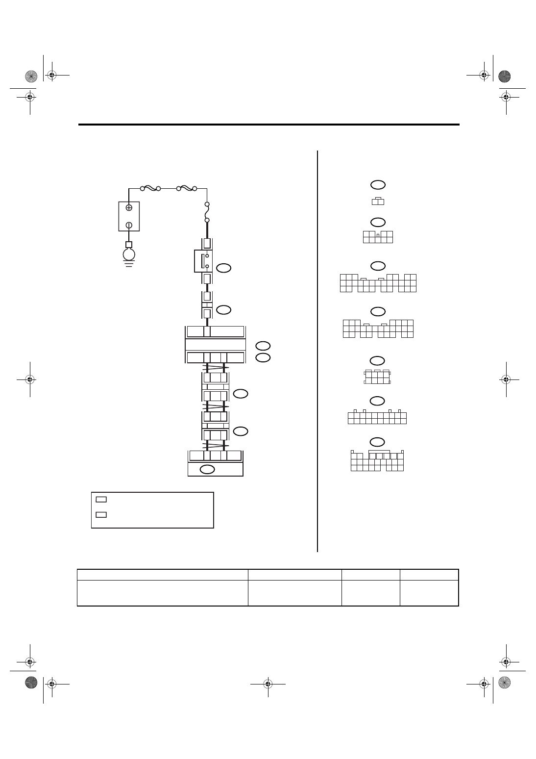
• RHD model
Step
Check
Yes
No
1
CHECK DTC.
Does the DTC of CAN commu-
nication appear in the on-board
diagnostics test mode?
Perform the diag-
nosis according to
DTC.
AT-03159
B64
B159
B280
B:
B281
C:
C23
B20
B30
8
B352
2
4
B53
B352
B53
10
9
8
7
6
5
4
3
2
1
20
19
18
17
16
15
14
13
12
11
B54
8
3
4
5
6
7
2
1
18 19 20
17
16
15
14
13
12
11
10
9
24
23
22
21
2
5
1
9
3
12
TCM
B54
MAIN SBF
SBF-2
No.8
E
B
A
TTER
Y
STOP LIGHT
SWITCH
JOINT
CONNECTOR
JOINT
CONNECTOR
JOINT
CONNECTOR
BODY INTEGRATED
MODULE
2
1
3 4
8
7
6
5
B159
2
1
3 4
8 9
7
6
5
B280
8
7
6
5
4
3
2
1
22
23
21
20
19
16
15
14
13
12
11
10
9
17
30
18
29
28
27
26
25
24
B281
8
7
6
5
4
3
2
1
21
22
20
19
16
15
14
13
12
11
10
9
17 18
28
27
26
25
24
23
B64
2
1
C:
B:
6
2
*
2
*
1
*
1
*
1
*
: TERMINAL No. RANDOM ARRANGEMENT
AMONG 8,18, AND 19
2
*
: TERMINAL No. RANDOM ARRANGEMENT
AMONG 9,10, AND 20
4AT(diag)-51
AUTOMATIC TRANSMISSION (DIAGNOSTICS)
Diagnostic Procedure with Diagnostic Trouble Code (DTC)
2
CHECK FUSE.
1) Turn the ignition switch to OFF.
2) Remove the fuse (No. 8).
Is the fuse (No. 8) blown out?
Replace the fuse
(No. 8). If the
replaced fuse (No.
8) has blown out
easily, repair the
short circuit of har-
ness between fuse
(No. 8) and stop
light switch.
3
CHECK BODY INTEGRATED MODULE.
1) Turn the ignition switch to OFF.
2) Connect the Subaru Select Monitor to data
link connector.
3) Turn the ignition switch to ON. (engine
OFF)
4) Turn the Subaru Select Monitor power
switch to ON.
5) Depress the brake pedal.
6) Read the data of brake pedal switch using
Subaru Select Monitor. <Ref. to LAN(diag)-14,
OPERATION, Subaru Select Monitor.>
Is ON displayed?
4
CHECK TCM.
Read the data of brake pedal switch using
Subaru Select Monitor. <Ref. to 4AT(diag)-16,
OPERATION, Subaru Select Monitor.>
Is ON displayed?
A temporary poor
contact of connec-
tor or harness may
be the cause.
Check the poor
contact.
Replace the TCM.
<Ref. to 4AT-66,
Transmission Con-
trol Module
(TCM).>
5
CHECK BODY INTEGRATED MODULE IN-
PUT SIGNAL.
1) Depress the brake pedal.
2) Disconnect the connector from body inte-
grated module.
3) Measure the voltage of harness between
body integrated module and stop light switch.
Connector & terminal
LHD model (With cruise control)
(B281) No. 23 (+) — (B65) No. 3 (
−
):
LHD model (Without cruise control)
(B281) No. 23 (+) — (B64) No. 2 (
−
):
RHD model
(B281) No. 23 (+) — (B64) No. 2 (
−
):
Is the voltage more than 10 V? Go to step 8.
6
CHECK HARNESS CONNECTOR BETWEEN
BODY INTEGRATED MODULE AND STOP
LIGHT SWITCH.
1) Turn the ignition switch to OFF.
2) Disconnect the connector from stop light
switch.
3) Measure the resistance of harness
between body integrated module and stop light
switch.
Connector & terminal
LHD model (With cruise control)
(B281) No. 23 — (B65) No. 3:
LHD model (Without cruise control)
(B281) No. 23 — (B64) No. 2:
RHD model
(B281) No. 23 — (B64) No. 2:
Is the resistance less than 1
Ω?
Repair the open
circuit of harness
between body inte-
grated module and
stop light switch.
Step
Check
Yes
No
4AT(diag)-52
AUTOMATIC TRANSMISSION (DIAGNOSTICS)
Diagnostic Procedure with Diagnostic Trouble Code (DTC)
7
CHECK HARNESS CONNECTOR BETWEEN
BODY INTEGRATED MODULE AND STOP
LIGHT SWITCH.
Measure the resistance of harness between
body integrated module and stop light switch.
Connector & terminal
(B281) No. 23 — Chassis ground:
Is the resistance more than 1
M
Ω?
Repair the short
circuit of harness
between body inte-
grated module and
stop light switch.
8
CHECK POOR CONTACT.
Is there poor contact in input
signal of brake switch?
Repair the poor
contact.
Check the body
integrated module.
Step
Check
Yes
No
Нет комментариевНе стесняйтесь поделиться с нами вашим ценным мнением.
Текст