Subaru Legacy (2005 year). Service manual — part 816
VDC(diag)-129
VEHICLE DYNAMICS CONTROL (VDC) (DIAGNOSTICS)
Diagnostic Procedure with Diagnostic Trouble Code (DTC)
2
CHECK PRESSURE SENSOR POWER SUP-
PLY.
1) Turn the ignition switch to OFF.
2) Disconnect the connector from pressure
sensor.
3) Turn the ignition switch to ON.
4) Measure the voltage between pressure
sensor connector and chassis ground.
Connector & terminal
(B348) No. 3 (+) — Chassis ground (
−
):
Is the voltage 4.75 — 5.25 V?
3
CHECK OUTPUT VOLTAGE OF VDCCM&H/
U.
Measure the voltage between VDCCM&H/U
and chassis ground.
Connector & terminal
(B310) No. 27 (+) — Chassis ground (
−
):
Is the voltage 4.75 — 5.25 V?
Repair the har-
ness between
pressure sensor
and VDCCM&H/U.
4
CHECK POOR CONTACT IN CONNECTORS. Is there poor contact in con-
nector?
Correct or replace
the connector.
5
CHECK GROUND CIRCUIT OF PRESSURE
SENSOR.
Measure the resistance between pressure
sensor and chassis ground.
Connector & terminal
(B348) No. 1 — Chassis ground:
Is the resistance less than 0.5
Ω?
6
CHECK GROUND CIRCUIT OF VDCCM&H/U.
Measure the resistance between VDCCM&H/U
and chassis ground.
Connector & terminal
(B310) No. 12 — Chassis ground:
Is the resistance less than 0.5
Ω?
Repair the har-
ness between
pressure sensor
and VDCCM&H/U.
7
CHECK POOR CONTACT IN CONNECTORS. Is there poor contact in con-
nector?
Correct or replace
the connector.
8
CHECK PRESSURE SENSOR HARNESS.
1) Turn the ignition switch to OFF.
2) Disconnect the connector from VDCCM&H/
U.
3) Measure the resistance between
VDCCM&H/U and pressure sensor.
Connector & terminal
(B310) No. 11 — (B348) No. 2:
Is the resistance less than 0.5
Ω?
Repair the har-
ness between
pressure sensor
and VDCCM&H/U.
9
CHECK GROUND SHORT OF HARNESS.
Measure the resistance between VDCCM&H/U
connector and chassis ground.
Connector & terminal
(B310) No. 11 — Chassis ground:
Is the resistance more than 1
M
Ω?
Repair the har-
ness between
pressure sensor
and VDCCM&H/U.
10
CHECK VDCCM&H/U.
1) Connect all the connectors.
2) Perform the clear memory mode.
3) Perform the inspection mode.
4) Read the DTC.
Is DTC displayed?
Replace the
VDCCM&H/U.
<Ref. to VDC-7,
VDC Control Mod-
ule and Hydraulic
Control Unit
(VDCCM&H/U).>
11
CHECK OTHER DTC DETECTION.
Is any other DTC displayed?
Perform the diag-
nosis according to
DTC.
Temporary poor
contact occurs.
Step
Check
Yes
No
VDC(diag)-130
VEHICLE DYNAMICS CONTROL (VDC) (DIAGNOSTICS)
Diagnostic Procedure with Diagnostic Trouble Code (DTC)
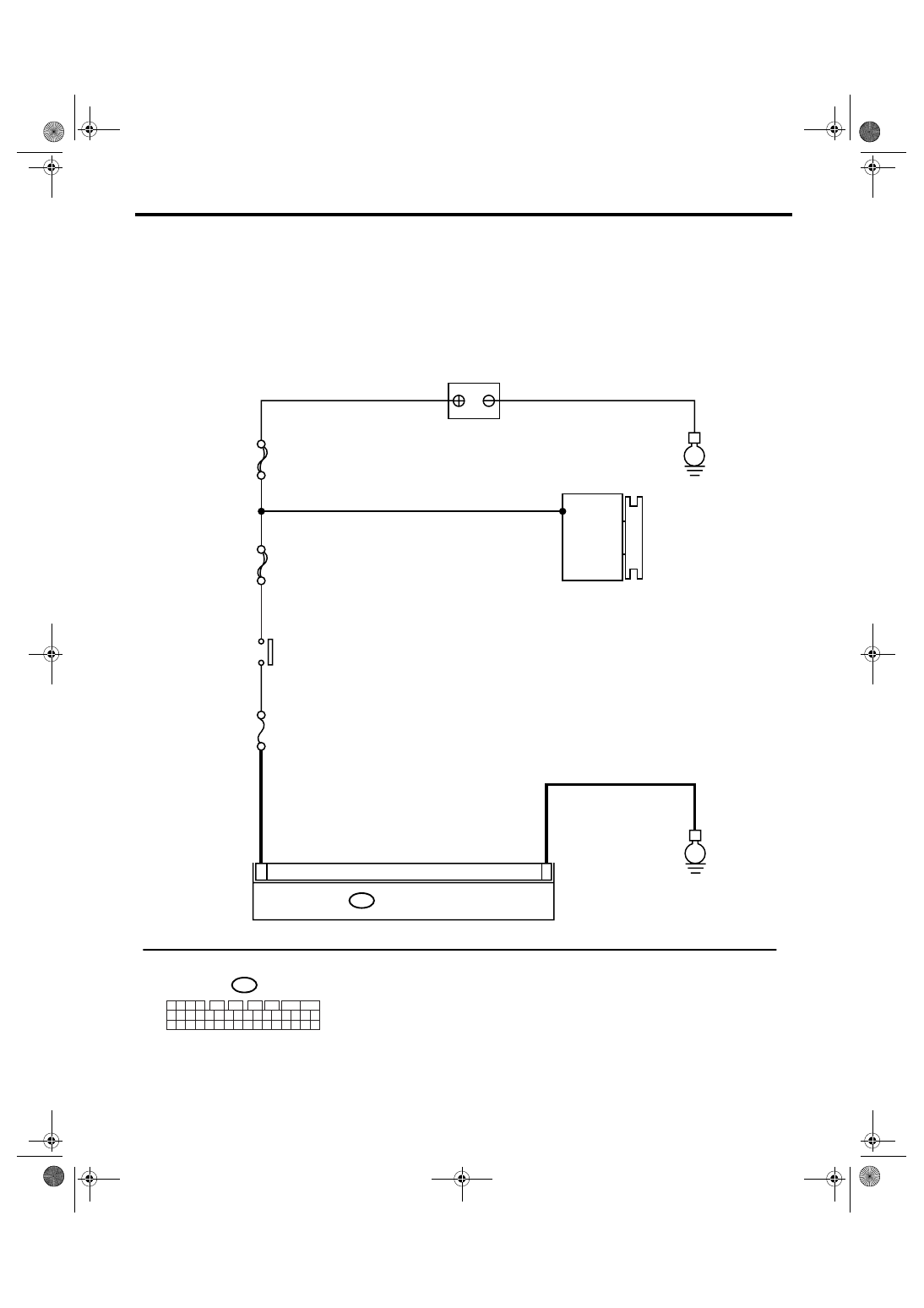
BK:DTC C0074 PRESSURE SENSOR POWER MALFUNCTION
DTC DETECTING CONDITION:
Defective pressure sensor
TROUBLE SYMPTOM:
• ABS does not operate.
• VDC does not operate.
WIRING DIAGRAM:
VDC00309
MAIN SBF
SBF-6
No.33
B310
B310
E
E
6
14
VDCCM & H/U
1 2 3 4
11 12 13 14
27 28 29 30
15 16 17 18
31 32 33 34
19 20 21 22
35 36 37 38
23 24 25 26
39 40 41 42
5
6
7
8
9
10
BATTERY
GENERATOR
IGNITION
SWITCH
VDC(diag)-131
VEHICLE DYNAMICS CONTROL (VDC) (DIAGNOSTICS)
Diagnostic Procedure with Diagnostic Trouble Code (DTC)
BL:DTC C0081 SYSTEM MALFUNCTION
DTC DETECTING CONDITION:
VDC long time sequential control
TROUBLE SYMPTOM:
• ABS does not operate.
• VDC does not operate.
Step
Check
Yes
No
1
CHECK POOR CONTACT IN CONNECTORS.
Check if there is poor contact in VDCCM&H/U
power supply circuit.
Is there poor contact?
Repair the con-
nector.
2
CHECK VDCCM&H/U POWER SUPPLY CIR-
CUIT.
1) Turn the ignition switch to OFF.
2) Disconnect the VDCCM&H/U connector.
3) Turn the ignition switch to ON.
4) Measure the voltage between VDCCM&H/
U connector terminals.
Connector & terminal
(B310) No. 14 (+) — (B310) No. 6 (
−
):
Is the voltage 10 — 15 V?
Check the power
supply circuit in
VDCCM&H/U.
3
CHECK VDCCM&H/U.
1) Connect all the connectors.
2) Perform the clear memory mode.
3) Perform the inspection mode.
4) Read the DTC.
Is the same DTC displayed?
Replace the
VDCCM&H/U.
<Ref. to VDC-7,
VDC Control Mod-
ule and Hydraulic
Control Unit
(VDCCM&H/U).>
4
CHECK OTHER DTC DETECTION.
Is any other DTC displayed?
Perform the diag-
nosis according to
DTC.
It results from a
temporary noise
interference.
Step
Check
Yes
No
1
CHECK POOR CONTACT IN CONNECTOR. Is there poor contact in the
VDCCM&H/U connector and
yaw rate & lateral G sensor
connector?
Repair the con-
nector.
2
CHECK VDCCM&H/U.
1) Replace the yaw rate & lateral G sensor.
2) Connect all the connectors.
3) Perform the clear memory mode.
4) Perform the inspection mode.
5) Read the DTC.
Is the same DTC displayed?
Replace the
VDCCM&H/U.
Malfunction is
found in original
yaw rate & lateral
G sensor.
VDC(diag)-132
VEHICLE DYNAMICS CONTROL (VDC) (DIAGNOSTICS)
General Diagnostic Table
13.General Diagnostic Table
A: INSPECTION
Symptom
Main probable cause
Other probable cause
Poor brake per-
formance
Long braking/
stopping dis-
tance
• VDCCM&H/U
• Brake pad
• Aeration to brake line
• Tire specifications, tire wear and air
pressures
• Incorrect wiring or piping connections
• Defective ABS wheel speed sensor or sensor
gap
• Defective steering angle sensor or improper
neutral position
• Defective yaw rate & lateral G sensor or
improper installation
• Master cylinder
• Brake caliper
• Disc rotor
• Brake pipe
• Brake booster
Wheel lock
• VDCCM&H/U
• Defective ABS wheel speed sensor or
sensor gap
• Incorrect wiring or piping connections
• Defective steering angle sensor or improper
neutral position
• Defective yaw rate & lateral G sensor or
improper installation
• Brake caliper
• Brake pipe
Brake drag
• VDCCM&H/U
• Defective ABS wheel speed sensor or
sensor gap
• Master cylinder
• Brake caliper
• Parking brake
• Axle and wheels
• Brake pedal play
• Defective steering angle sensor or improper
neutral position
• Defective yaw rate & lateral G sensor or
improper installation
• Brake pad
• Brake pipe
Long brake
pedal stroke
• Aeration to brake line
• Brake pedal play
• VDCCM&H/U
• Master cylinder
• Brake caliper
• Brake pad
• Brake pipe
• Brake booster
Vehicle vertical
pitching
• VDCCM&H/U
• Road surface (uneven)
• Suspension play or fatigue (reduced
damping)
• Incorrect wiring or piping connections
• Defective ABS wheel speed sensor or sensor
gap
• Defective steering angle sensor or improper
neutral position
• Defective yaw rate & lateral G sensor or
improper installation
Poor brake per-
formance
Unstable or
uneven braking
• VDCCM&H/U
• Defective ABS wheel speed sensor or
sensor gap
• Brake caliper
• Brake pad
• Road surface (uneven)
• Tire specifications, tire wear and air
pressures
• Incorrect wiring or piping connections
• Defective ABS wheel speed sensor or sensor
gap
• Defective steering angle sensor or improper
neutral position
• Defective yaw rate & lateral G sensor or
improper installation
• Master cylinder
• Disc rotor
• Brake pipe
• Axle and wheels
• Road with crowns or banks
• Suspension play or fatigue (poor damping)
Нет комментариевНе стесняйтесь поделиться с нами вашим ценным мнением.
Текст