Subaru Legacy (2005 year). Service manual — part 1000
EI-57
EXTERIOR/INTERIOR TRIM
Instrument Panel Assembly
15) Disconnect the connectors, and remove the in-
strument panel from vehicle body.
NOTE:
• If necessary, make matching marks for easy re-
assembly.
• When storing the removed instrument panel, be
sure to prepare a table or the like to put instrument
panel on to prevent damage.
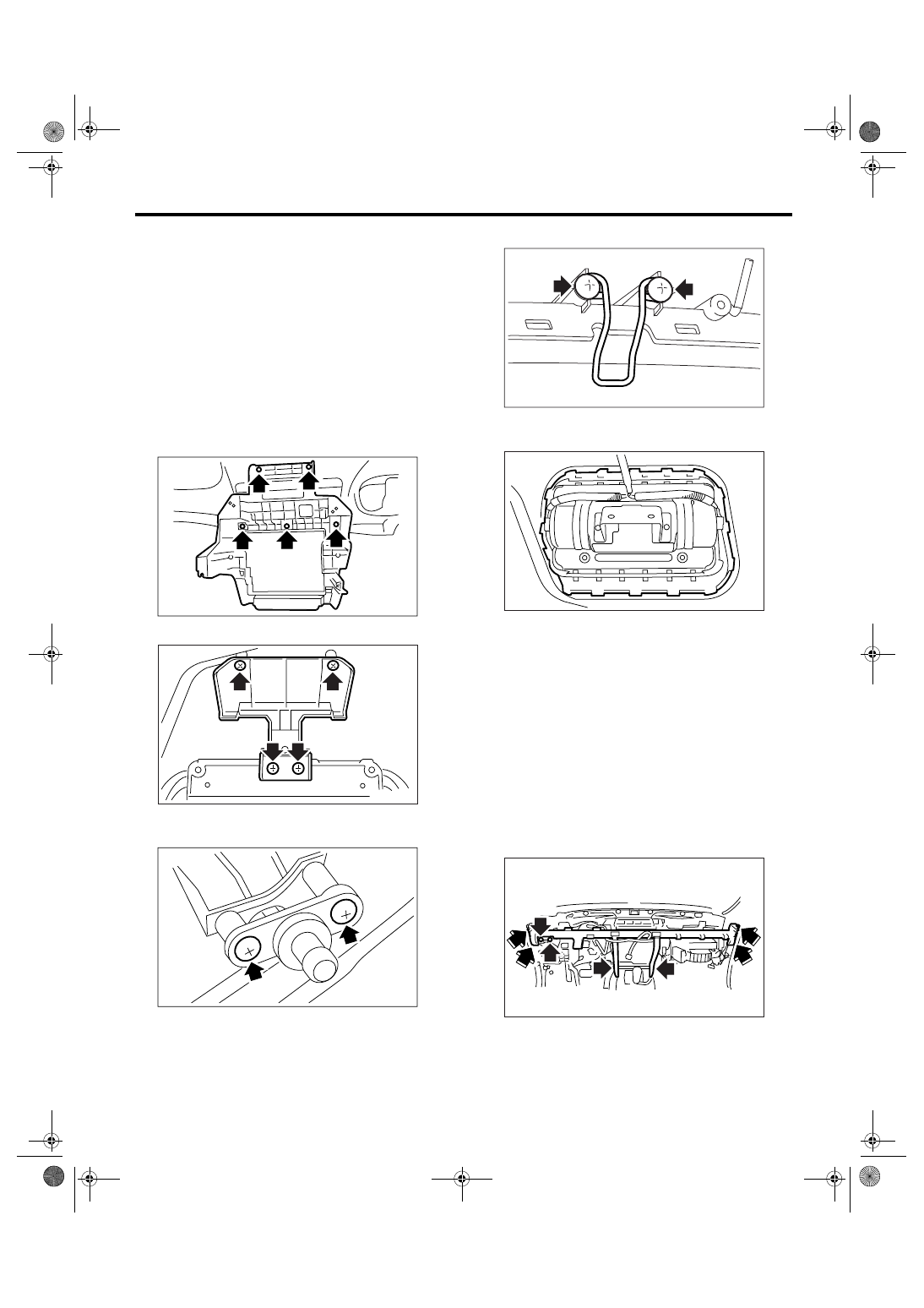
16) Remove the side air vent grille. <Ref. to AC-46,
REMOVAL, Air Vent Grille.>
17) Remove the heater vent duct. <Ref. to AC-48,
REMOVAL, Heater Vent Duct.>
18) Loosen the screws to remove center console
frame.
19) Loosen the screws to remove meter bracket.
20) Loosen the screws to remove instrument panel
matching pins.
21) Loosen the screws to remove glove box striker.
22) Remove the pawl, and remove the passenger’s
airbag module.
2. STEERING SUPPORT BEAM
1) Remove the instrument panel. <Ref. to EI-56,
INSTRUMENT PANEL (EXCLUDING STEERING
SUPPORT BEAM), REMOVAL, Instrument Panel
Assembly.>
2) Remove the steering shaft assembly. <Ref. to
PS-24, REMOVAL, Tilt Steering Column.>
3) Remove each harness clip, and remove the har-
ness from steering support beam.
NOTE:
If necessary, make matching marks for easy reas-
sembly.
4) Remove the bolts and remove steering support
beam.
EI-00774
EI-00612
EI-00613
EI-00614
EI-00615
EI-00775
EI-58
EXTERIOR/INTERIOR TRIM
Instrument Panel Assembly
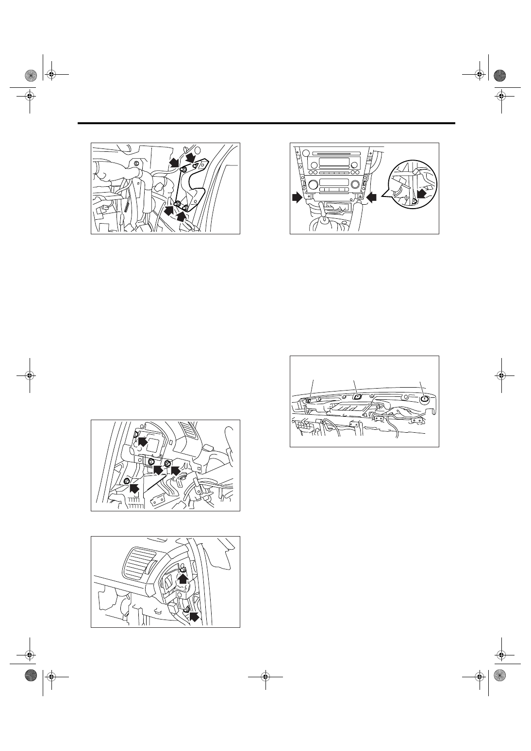
5) Remove the steering support beam bracket.
3. INSTRUMENT PANEL ASSEMBLY (IN-
CLUDING STEERING SUPPORT BEAM)
CAUTION:
Be careful to the harness of airbag system
when servicing the instrument panel. Damage
may cause the system malfunction.
1) Remove the front pillar upper trim. <Ref. to EI-
62, REMOVAL, Upper Inner Trim.>
2) Remove the center console. <Ref. to EI-54, RE-
MOVAL, Center Console.>
3) Remove the instrument panel lower cover. <Ref.
to EI-50, REMOVAL, Instrument Panel Lower Cov-
er.>
4) Remove the glove box. <Ref. to EI-51, REMOV-
AL, Glove Box.>
5) Remove the steering shaft assembly. <Ref. to
PS-24, REMOVAL, Tilt Steering Column.>
6) Remove the driver’s side instrument panel side
cover, and remove the bolts.
7) Remove the bolts in the side face of passenger’s
side instrument panel.
8) Loosen the bolts on the center console side.
9) Disconnect each connector, and remove the in-
strument assembly.
NOTE:
If necessary, make matching marks for easy reas-
sembly.
B: INSTALLATION
1. INSTRUMENT PANEL (EXCLUDING
STEERING SUPPORT BEAM)
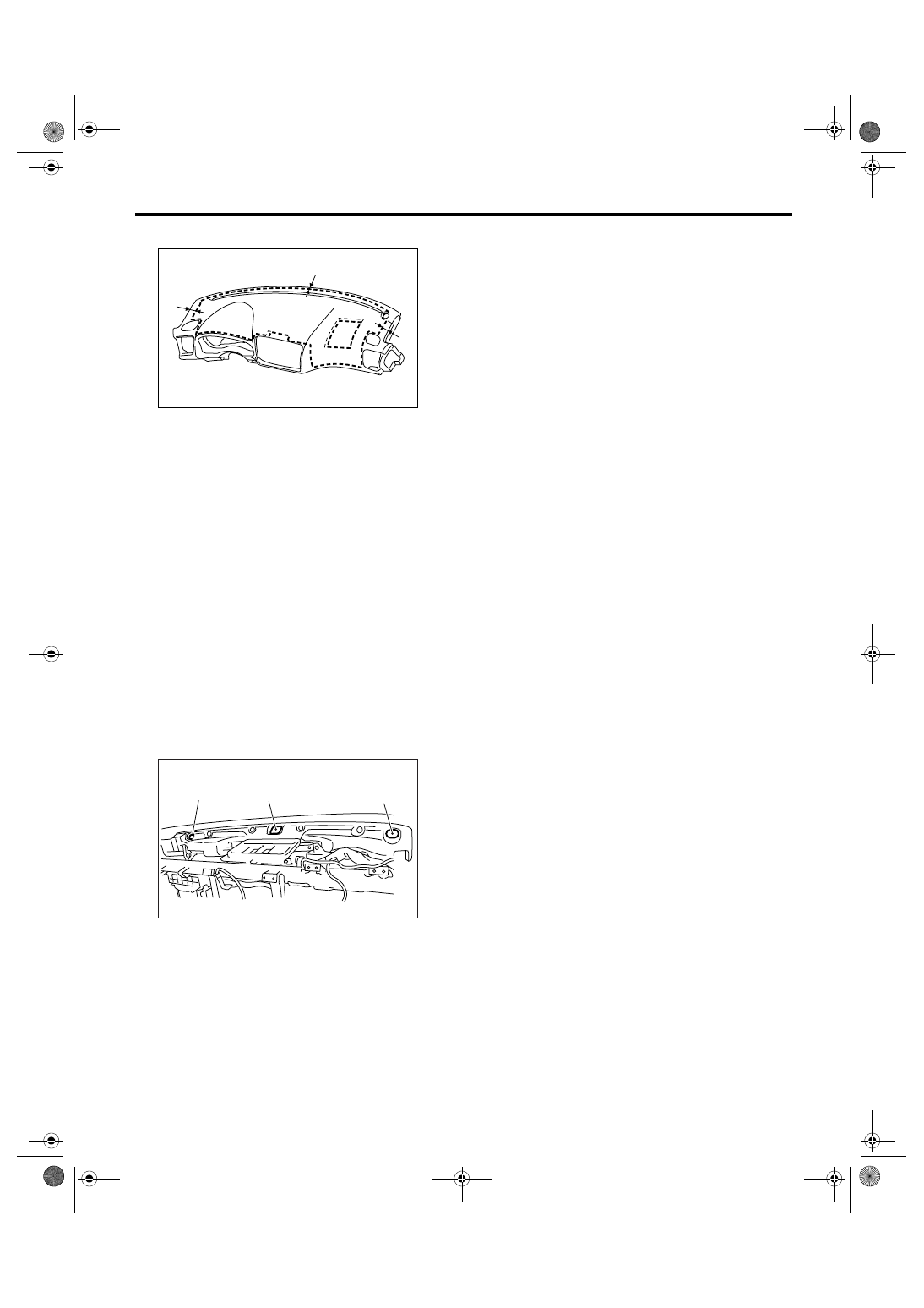
1) Insert the matching pins (three places) on the in-
strument panel tip into the grommet (A) and (B) on
the body panel side.
2) Check that the matching pins are inserted se-
curely, then route the harness.
3) Tighten the instrument panel with screw, and re-
check the installation condition of instrument panel
and harness routing.
4) Install in the reverse order of removal.
NOTE:
How to install insulator and pad;
• Adhesive
Use polyurethane adhesive. When assembling the
instrument panel assembly, wait until the adhesive
has evaporated to prevent filling of the smell in the
compartment.
• Double-sided tape
Use commercial double-sided tape. (Use double-
sided adhesive tape having extra-strength.)
EI-00617
EI-00776
EI-00777
EI-00620
EI-00621
(B)
(B)
(A)
EI-59
EXTERIOR/INTERIOR TRIM
Instrument Panel Assembly
• Location
Make clearance for 10 mm from instrument panel
front edge, and 40 mm from both side edges when
taping.
2. STEERING SUPPORT BEAM
1) Temporarily tighten the steering support beam
with bolt, and then route the harness.
2) Make sure that there is no mutual interference in
each pedal, and then tighten each bolt.
Tightening torque:
25 N
⋅
m (25.5 kgf-m, 18.4 ft-lb)
3) Install in the reverse order of removal.
3. INSTRUMENT PANEL ASSEMBLY (IN-
CLUDING STEERING SUPPORT BEAM)
1) Insert the matching pins (three places) on the in-
strument panel tip into the grommet (A) and (B) on
the body panel side.
2) Check that the matching pins are inserted se-
curely, and then route the harness.
3) Temporarily tighten the steering support beam
with bolt, and then route the harness.
4) Make sure that there is no mutual interference in
each pedal, and then tighten each bolt.
Tightening torque:
25 N
⋅
m (25.5 kgf-m, 18.4 ft-lb)
5) Install in the reverse order of removal.
(1) 10 mm (0.39 in)
(2) 40 mm (1.57 in)
EI-01087
(2)
(1)
(2)
EI-00621
(B)
(B)
(A)
EI-60
EXTERIOR/INTERIOR TRIM
Lower Inner Trim
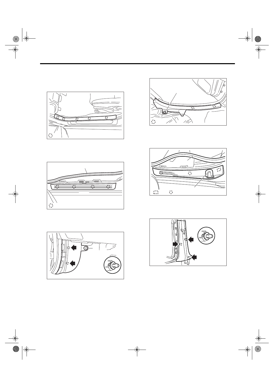
24.Lower Inner Trim
A: REMOVAL
1) Remove the hooks, and remove the inside scuff
plate.
2) Remove the door molding (A), and remove the
outside scuff plate.
3) Remove the clip (A), and remove the front pillar
lower trim.
4) Remove the rear seat cushion. <Ref. to SE-14,
REMOVAL, Rear Seat.>
5) Remove the clip (A), and remove the inside scuff
plate.
6) Remove the door molding (A) and door catcher
cover (B), and then remove the outside scuff plate.
7) Remove the clips of center pillar lower trim.
(A) Hook
(B) Clip
EI-00778
: (A)
(A)
EI-00779
: (B)
(A)
EI-00780
(B) Hook
(C) Hook with plate clip
(D) Clip
(A)
EI-00781
: (B)
EI-00782
(A)
:(C)
:(D)
(B)
EI-00783
Нет комментариевНе стесняйтесь поделиться с нами вашим ценным мнением.
Текст