Subaru Legacy (2005 year). Service manual — part 278
ME(H4DOTC)-55
MECHANICAL
Crank Sprocket
18.Crank Sprocket
A: REMOVAL
1) Remove the V-belts. <Ref. to ME(H4DOTC)-40,
REMOVAL, V-belt.>
2) Remove the crank pulley.
<Ref. to ME(H4DOTC)-43, REMOVAL, Crank Pul-
ley.>
3) Remove the timing belt cover.
<Ref. to ME(H4DOTC)-45, REMOVAL, Timing Belt
Cover.>
4) Remove the timing belt.
<Ref. to ME(H4DOTC)-46, REMOVAL, Timing
Belt.>
5) Remove the cam sprocket.
<Ref. to ME(H4DOTC)-54, REMOVAL, Cam
Sprocket.>
6) Remove the crank sprocket.
B: INSTALLATION
1) Install the crank sprocket.
2) Install the cam sprocket.
<Ref. to ME(H4DOTC)-54, INSTALLATION, Cam
Sprocket.>
3) Install the timing belt.
<Ref. to ME(H4DOTC)-48, INSTALLATION, Tim-
ing Belt.>
4) Install the timing belt cover.
<Ref. to ME(H4DOTC)-45, INSTALLATION, Tim-
ing Belt Cover.>
5) Install the crank pulley. <Ref. to ME(H4DOTC)-
43, INSTALLATION, Crank Pulley.>
6) Install the V-belts. <Ref. to ME(H4DOTC)-40,
INSTALLATION, V-belt.>
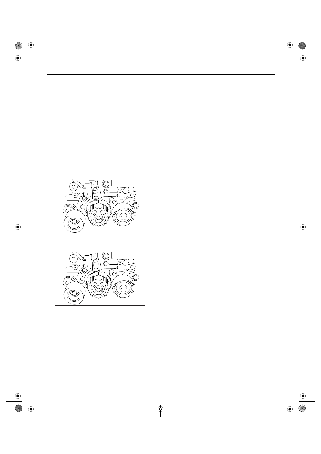
C: INSPECTION
1) Check the crank sprocket teeth for abnormal
wear and scratches.
2) Make sure there is no free play between crank
sprocket and key.
3) Check the crank sprocket protrusion used for
sensor for damage and contamination of foreign
matter.
ME-00103
ME-00103
ME(H4DOTC)-56
MECHANICAL
Camshaft
19.Camshaft
A: REMOVAL
1) Remove the V-belts. <Ref. to ME(H4DOTC)-40,
REMOVAL, V-belt.>
2) Remove the crank pulley. <Ref. to
ME(H4DOTC)-43, REMOVAL, Crank Pulley.>
3) Remove the timing belt cover.
<Ref. to ME(H4DOTC)-45, REMOVAL, Timing Belt
Cover.>
4) Remove the timing belt. <Ref. to ME(H4DOTC)-
46, REMOVAL, Timing Belt.>
5) Remove the cam sprocket. <Ref. to
ME(H4DOTC)-54, REMOVAL, Cam Sprocket.>
6) Remove the crank sprocket. <Ref. to
ME(H4DOTC)-55, REMOVAL, Crank Sprocket.>
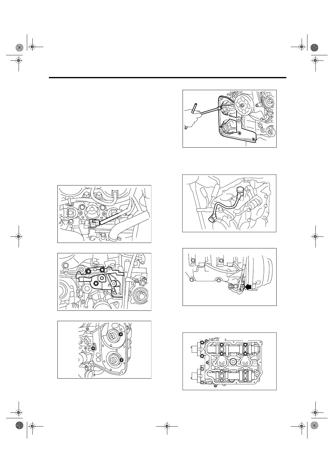
7) Disconnect the oil flow control solenoid valve as-
sembly connector.
8) Remove the tensioner bracket.
9) Remove the timing belt cover No. 2 (LH).
10) Remove the timing belt cover No. 2 (RH).
11) Remove the spark plug cords.
12) Remove the oil level gauge guide. (LH side)
13) Remove the rocker cover and gasket.
14) Remove the oil pipe.
15) Remove the camshaft position sensor on ex-
haust side.
16) Loosen the oil flow control solenoid valve as-
sembly and intake camshaft cap bolts equally, a lit-
tle at a time in alphabetical sequence shown in the
figure.
ME-00808
ME-00105
ME-00106
ME-00107
ME-00712
FU-01186
ME-00771
(A)
(E)
(F)
(B)
(D)
(C)
ME(H4DOTC)-57
MECHANICAL
Camshaft
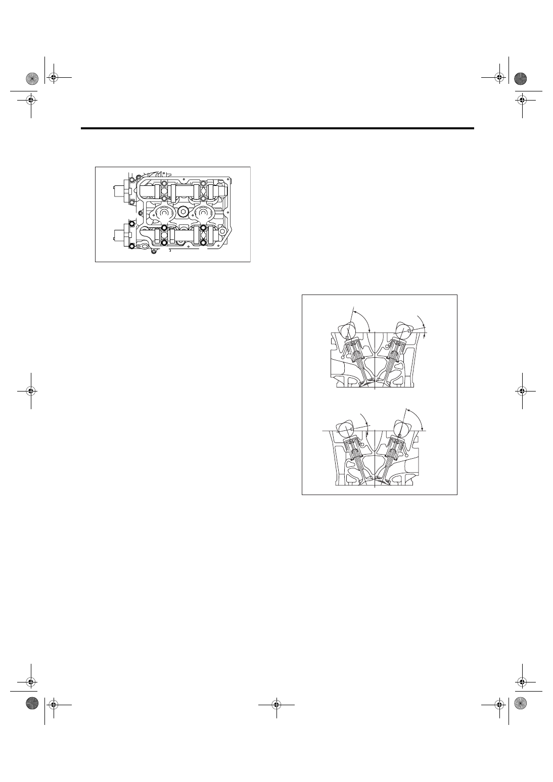
17) Loosen the exhaust camshaft cap bolts equal-
ly, a little at a time in alphabetical sequence shown
in the figure.
18) Remove the oil flow control solenoid valve as-
sembly, intake camshaft cap and camshaft.
19) Remove the exhaust camshaft caps and cam-
shaft.
NOTE:
Arrange the camshaft caps in order so that they
can be installed in their original positions.
20) Similarly, remove the camshafts (RH) and re-
lated parts.
B: INSTALLATION
1) Camshaft installation:
Apply engine oil to the cylinder head at camshaft
bearing location before installing the camshaft. In-
stall the camshaft so that each valve is close to or in
contact with “base circle” of cam lobe.
NOTE:
• When the camshafts are positioned as shown in
the figure, camshafts need to be rotated at a mini-
mum to align with the timing belt during installation.
• Camshaft RH need not be rotated when set at
the position shown in the figure.
Intake camshaft (LH):
Rotate 80
° clockwise.
Exhaust camshaft (LH):
Rotate 45
° counterclockwise.
ME-00772
(A)
(E)
(F)
(B)
(D)
(C)
A Cylinder head (LH)
B Cylinder head (RH)
(a) Intake camshaft
(b) Exhaust camshaft
ME-00111
11
11
77.5
77.5
(a)
(b)
(a)
(b)
A
B
ME(H4DOTC)-58
MECHANICAL
Camshaft
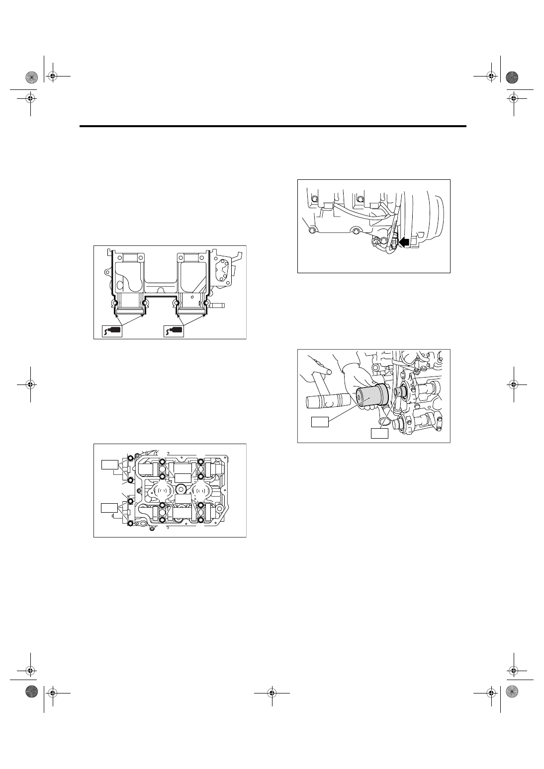
2) Camshaft cap and oil flow control solenoid valve
assembly installation:
(1) Apply small amount of liquid gasket to the
cap mating surface.
NOTE:
Do not apply liquid gasket excessively. Otherwise,
the excessive liquid gasket may come out and flow
toward oil seal, resulting in oil leaks.
Liquid gasket:
THREE BOND 1215 (Part No. 004403007) or
equivalent
(2) Apply engine oil to the cap bearing surface,
and install the cap on camshaft as shown by
identification mark.
(3) Gradually tighten the camshaft cap and oil
control valve assembly in at least two stages in
alphabetical sequence shown in the figure, and
then tighten to the specified torque.
Tightening torque:
T1: 20 N
⋅
m (2.0 kgf-m, 14.8 ft-lb)
T2: 9.75 N
⋅
m (1.0 kgf-m, 7.2 ft-lb)
(4) After tightening the camshaft cap, ensure
the camshaft rotates only slightly while holding it
at “base circle”.
3) Install the camshaft position sensor on exhaust
side.
Tightening torque:
6.4 N
⋅
m (0.65 kgf-m, 4.7 ft-lb)
4) Camshaft oil seal installation:
Apply grease to the new oil seal lips and press onto
the front end of camshaft by using ST1 and ST2.
NOTE:
Use a new oil seal.
ST1
499587600
OIL SEAL INSTALLER
ST2
499597200
OIL SEAL GUIDE
ME-00773
ME-00839
(G)
(C)
(A)
(K)
(L)
T2
(F)
(E)
T1
T1
(B)
(J)
(H)
(D)
(I)
T2
FU-01186
ME-00116
ST1
ST2
Нет комментариевНе стесняйтесь поделиться с нами вашим ценным мнением.
Текст