Subaru Legacy (2005 year). Service manual — part 338

EN(H4DOTC)(diag)-121
ENGINE (DIAGNOSTICS)
Diagnostic Procedure with Diagnostic Trouble Code (DTC)
Y: DTC P0245 TURBO/SUPER CHARGER WASTEGATE SOLENOID “A” LOW
DTC DETECTING CONDITION:
Immediately at fault recognition
TROUBLE SYMPTOM:
Erroneous idling
CAUTION:
After repair or replacement of faulty parts, perform Clear Memory Mode <Ref. to EN(H4DOTC)(diag)-
37, OPERATION, Clear Memory Mode.> and Inspection Mode <Ref. to EN(H4DOTC)(diag)-30, PROCE-
DURE, Inspection Mode.>.
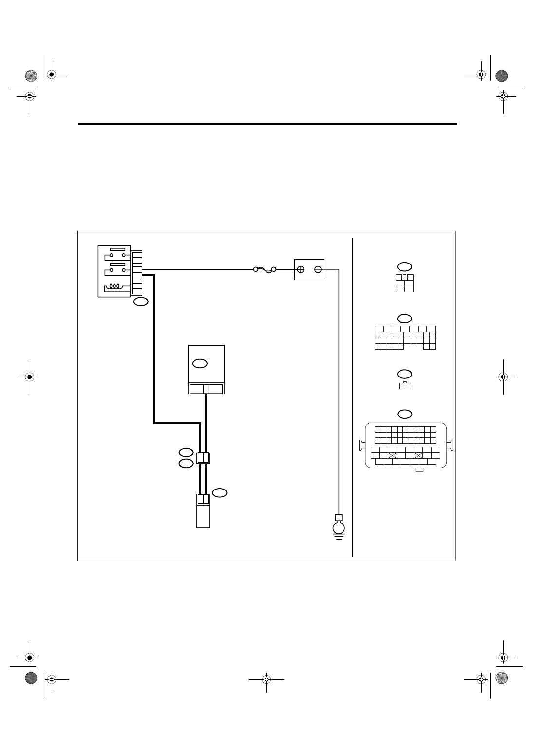
WIRING DIAGRAM:
EN-03525
B47
1
2
4
6
3
5
E
B47
B134
E64
B134
E64
ECM
32
1
2
SBF-4
3
4
1
2
5
6
1 2
5
6
7
8
2
1
9
4
3
10
24
22 23
25
11 12 13 14 15
26 27
28
16 17
18 19 20 21
33 34
29
32
30 31
MAIN RELAY
BATTERY
WASTEGATE
CONTROL SOLENOID
VALVE
B21
E2
40
48
B21
1 2 3 4
12 13 14 15
5 6 7 8
16 17 18 19
9 10 11
20 21 22
23 24 25 26 27 28 29 30 31 32 33
35
34
37
36
39
38
41
40
43
42
44
45
47
46
49
48
51
50
53
52
54
EN(H4DOTC)(diag)-122
ENGINE (DIAGNOSTICS)
Diagnostic Procedure with Diagnostic Trouble Code (DTC)
Step
Check
Yes
No
1
CHECK OUTPUT SIGNAL FROM ECM.
1) Turn the ignition switch to ON.
2) Measure the voltage between ECM and
chassis ground.
Connector & terminal
(B134) No. 32 (+) — Chassis ground (
−
):
Is the voltage more than 10 V? Even if the mal-
function indicator
light illuminates,
the circuit has
returned to a nor-
mal condition at
this time.
2
CHECK HARNESS BETWEEN WASTEGATE
CONTROL SOLENOID VALVE AND ECM
CONNECTOR.
1) Turn the ignition switch to OFF.
2) Disconnect the connectors from wastegate
control solenoid valve and ECM.
3) Measure the resistance of harness
between wastegate control solenoid valve con-
nector and engine ground.
Connector & terminal
(E64) No. 1 — Engine ground:
Is the resistance more than 1
M
Ω?
Repair the ground
short circuit of har-
ness between
ECM and waste-
gate control sole-
noid valve
connector.
3
CHECK HARNESS BETWEEN WASTEGATE
CONTROL SOLENOID VALVE AND ECM
CONNECTOR.
Measure the resistance of harness between
wastegate control solenoid valve of harness
connector and ECM.
Connector & terminal
(B134) No. 32 — (E64) No. 1:
Is the resistance less than 1
Ω?
Repair the open
circuit of harness
between ECM and
wastegate control
solenoid valve
connector.
NOTE:
In this case, repair
the following:
• Open circuit of
harness between
ECM and waste-
gate control sole-
noid valve
connector
4
CHECK WASTEGATE CONTROL SOLE-
NOID VALVE.
1) Remove the wastegate control solenoid
valve.
2) Measure the resistance between wastegate
control solenoid valve terminals.
Terminals
No. 1 — No. 2:
Is the resistance 30 — 34
Ω?
Replace the
wastegate control
solenoid valve.
<Ref. to
FU(H4DOTC)-31,
Wastegate Con-
trol Solenoid
Valve.>
5
CHECK POWER SUPPLY TO WASTEGATE
CONTROL SOLENOID VALVE.
1) Turn the ignition switch to ON.
2) Measure the voltage between wastegate
control solenoid valve and engine ground.
Connector & terminal
(E64) No. 2 (+) — Engine ground (
−
):
Is the voltage more than 10 V? Go to step 6.
Repair the open
circuit of harness
between main
relay and waste-
gate control sole-
noid valve
connector.
6
CHECK POOR CONTACT.
Check poor contact in wastegate control sole-
noid valve connector.
Is there poor contact in waste-
gate control solenoid valve
connector?
Repair the poor
contact in waste-
gate control sole-
noid valve
connector.
Replace the ECM.
<Ref. to
FU(H4DOTC)-34,
Engine Control
Module (ECM).>
EN(H4DOTC)(diag)-123
ENGINE (DIAGNOSTICS)
Diagnostic Procedure with Diagnostic Trouble Code (DTC)
Z: DTC P0246 TURBO/SUPER CHARGER WASTEGATE SOLENOID “A” HIGH
DTC DETECTING CONDITION:
Immediately at fault recognition
TROUBLE SYMPTOM:
Erroneous idling
CAUTION:
After repair or replacement of faulty parts, perform Clear Memory Mode <Ref. to EN(H4DOTC)(diag)-
37, OPERATION, Clear Memory Mode.> and Inspection Mode <Ref. to EN(H4DOTC)(diag)-30, PROCE-
DURE, Inspection Mode.>.
WIRING DIAGRAM:
EN-03525
B47
1
2
4
6
3
5
E
B47
B134
E64
B134
E64
ECM
32
1
2
SBF-4
3
4
1
2
5
6
1 2
5
6
7
8
2
1
9
4
3
10
24
22 23
25
11 12 13 14 15
26 27
28
16 17
18 19 20 21
33 34
29
32
30 31
MAIN RELAY
BATTERY
WASTEGATE
CONTROL SOLENOID
VALVE
B21
E2
40
48
B21
1 2 3 4
12 13 14 15
5 6 7 8
16 17 18 19
9 10 11
20 21 22
23 24 25 26 27 28 29 30 31 32 33
35
34
37
36
39
38
41
40
43
42
44
45
47
46
49
48
51
50
53
52
54
EN(H4DOTC)(diag)-124
ENGINE (DIAGNOSTICS)
Diagnostic Procedure with Diagnostic Trouble Code (DTC)
Step
Check
Yes
No
1
CHECK OUTPUT SIGNAL FROM ECM.
1) Turn the ignition switch to ON.
2) Measure the voltage between ECM and
chassis ground.
Connector & terminal
(B134) No. 32 (+) — Chassis ground (
−
):
Is the voltage more than 10 V? Go to step 3.
2
CHECK POOR CONTACT.
Check poor contact in ECM connector.
Is there poor contact in ECM
connector?
Repair the poor
contact in ECM
connector.
Replace the ECM.
<Ref. to
FU(H4DOTC)-34,
Engine Control
Module (ECM).>
3
CHECK HARNESS BETWEEN WASTEGATE
CONTROL SOLENOID VALVE AND ECM
CONNECTOR.
1) Turn the ignition switch to OFF.
2) Disconnect the connector from wastegate
control solenoid valve.
3) Turn the ignition switch to ON.
4) Measure the voltage between ECM and
chassis ground.
Connector & terminal
(B134) No. 32 (+) — Chassis ground (
−
):
Is the voltage more than 10 V? Repair the battery
short circuit of har-
ness between
ECM and waste-
gate control sole-
noid valve
connector. After
repair, replace the
ECM. <Ref. to
FU(H4DOTC)-34,
Engine Control
Module (ECM).>
4
CHECK WASTEGATE CONTROL SOLE-
NOID VALVE.
1) Turn the ignition switch to OFF.
2) Measure the resistance between wastegate
control solenoid valve terminals.
Terminals
No. 1 — No. 2:
Is the resistance less than 1
Ω?
Replace the
wastegate control
solenoid valve and
ECM. <Ref. to
FU(H4DOTC)-31,
Wastegate Con-
trol Solenoid
Valve.> <Ref. to
FU(H4DOTC)-34,
Engine Control
Module (ECM).>
5
CHECK POOR CONTACT.
Check poor contact in ECM connector.
Is there poor contact in ECM
connector?
Repair the poor
contact in ECM
connector.
Replace the ECM.
<Ref. to
FU(H4DOTC)-34,
Engine Control
Module (ECM).>
Нет комментариевНе стесняйтесь поделиться с нами вашим ценным мнением.
Текст