Subaru Legacy (2005 year). Service manual — part 283
ME(H4DOTC)-75
MECHANICAL
Cylinder Block
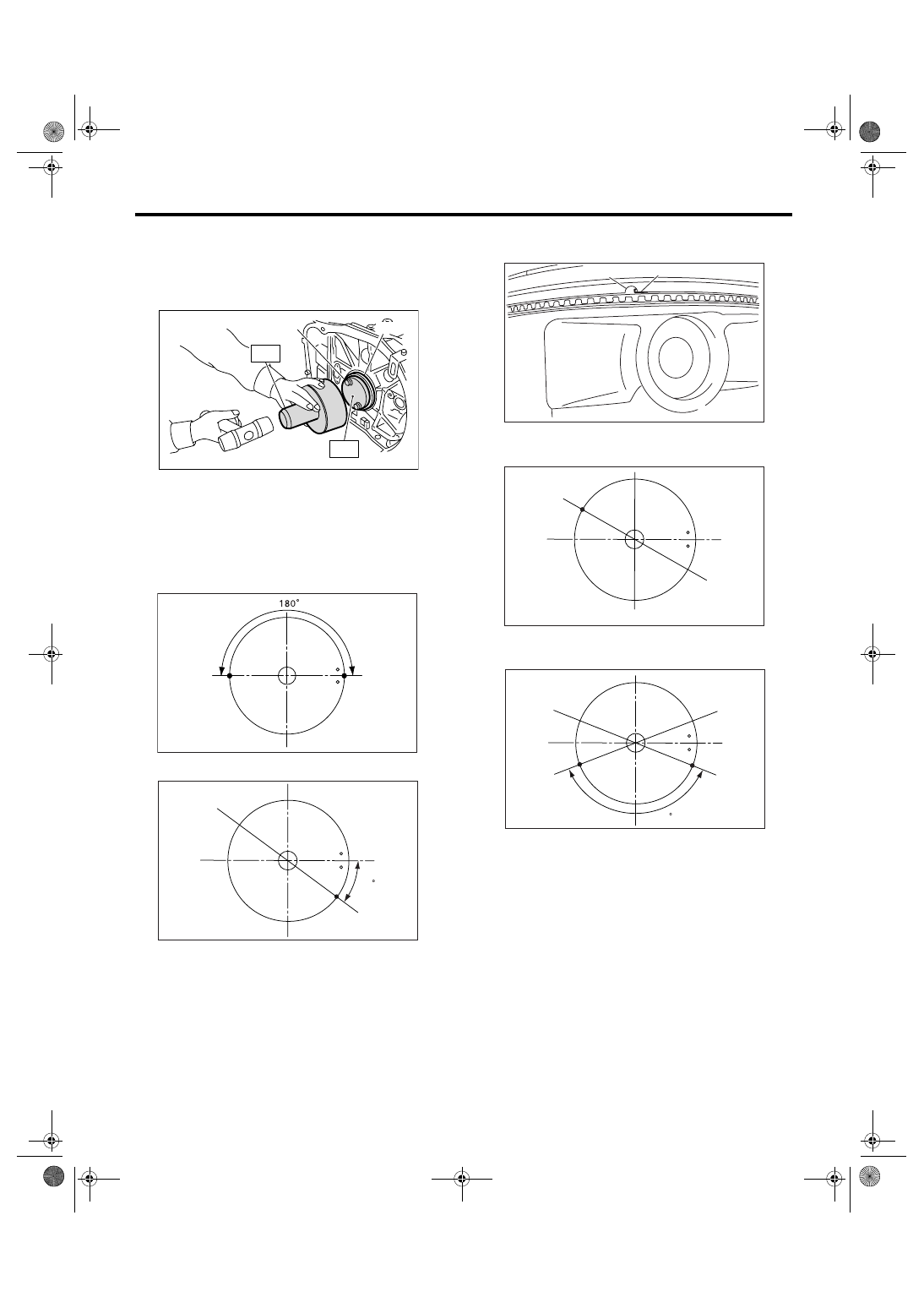
12) Install the rear oil seal using ST1 and ST2.
ST1
499597100
CRANKSHAFT OIL SEAL
GUIDE
ST2
499587200
CRANKSHAFT OIL SEAL IN-
STALLER
13) Position the top ring gap at (A) or (B) in the fig-
ure.
14) Position the second ring gap at 180
° on the re-
verse side for the top ring gap.
15) Position the upper rail gap at (C) in the figure.
16) Align the upper rail spin stopper (E) to the side
hole (D) on the piston.
17) Position the expander gap at 180
° on the re-
verse side of (C) that shown (F) in the figure.
18) Position the lower rail gap at 120
° clockwise of
(C) that shown (G) in the figure.
CAUTION:
• Ensure ring gaps do not face the same direc-
tion.
• Ensure ring gaps are not within the piston
skirt area.
(A) Rear oil seal
(B) Flywheel attaching bolt
ME-00148
ST1
ST2
(B)
(A)
ME-00718
(A)
(B)
ME-02087
(C)
25
ME-02392
(E)
(D)
ME-02088
(F)
ME-02089
120
(C)
(G)
ME(H4DOTC)-76
MECHANICAL
Cylinder Block
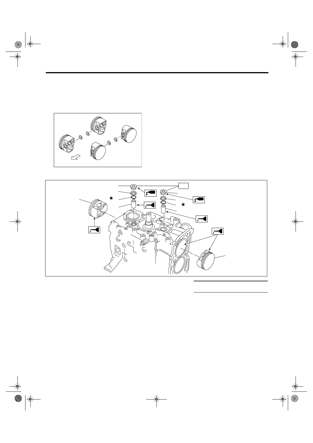
19) Install the snap ring.
Install snap rings in the piston holes located oppo-
site to the service holes in cylinder block, when po-
sitioning all pistons in the corresponding cylinders.
NOTE:
Use new snap rings.
(A) Forward
ME-00154
#4
#3
#2
#1
(A)
(1)
Piston
(4)
Gasket
Tightening torque: N
⋅
m (kgf-m, ft-lb)
(2)
Piston pin
(5)
Service hole plug
T: 70 (7.1, 51.6)
(3)
Snap ring
ME-00155
(1)
(1)
(2)
(2)
(3)
(3)
(4)
(4)
(5)
(5)
T

ME(H4DOTC)-77
MECHANICAL
Cylinder Block
20) Installation of piston:
(1) Place the #1 and #2 cylinder side upward.
(2) Using the ST1, turn the crankshaft so that
#1 and #2 connecting rods are set at bottom
dead center.
ST1
499987500
CRANKSHAFT SOCKET
(3) Apply a coat of engine oil to the pistons and
cylinders and insert pistons in their cylinders us-
ing ST2.
ST2
398744300
PISTON GUIDE
NOTE:
Piston front mark faces towards the front of engine.
21) Installing piston pin:
(1) Apply a coat of engine oil to ST3 before in-
sertion, and then insert it into the service hole to
align piston pin hole with connecting rod small
end.
ST3
499017100
PISTON PIN GUIDE
(2) Apply a coat of engine oil to piston pin, and
insert the piston pin into piston and connecting
rod through service hole.
(3) Install the snap ring.
NOTE:
Use new snap rings.
(4) Apply liquid gasket around the service hole
plug.
Liquid gasket:
THREE BOND 1215 (Part No. 004403007) or
equivalent
(5) Install the service hole plug and gasket.
NOTE:
Use a new gasket.
(A) Front mark
ME-00157
ST2
ST1
ME-00722
(A)
ME-00158
ST1
ST3
ME-00159
ME-00160
ME-00140
ME(H4DOTC)-78
MECHANICAL
Cylinder Block
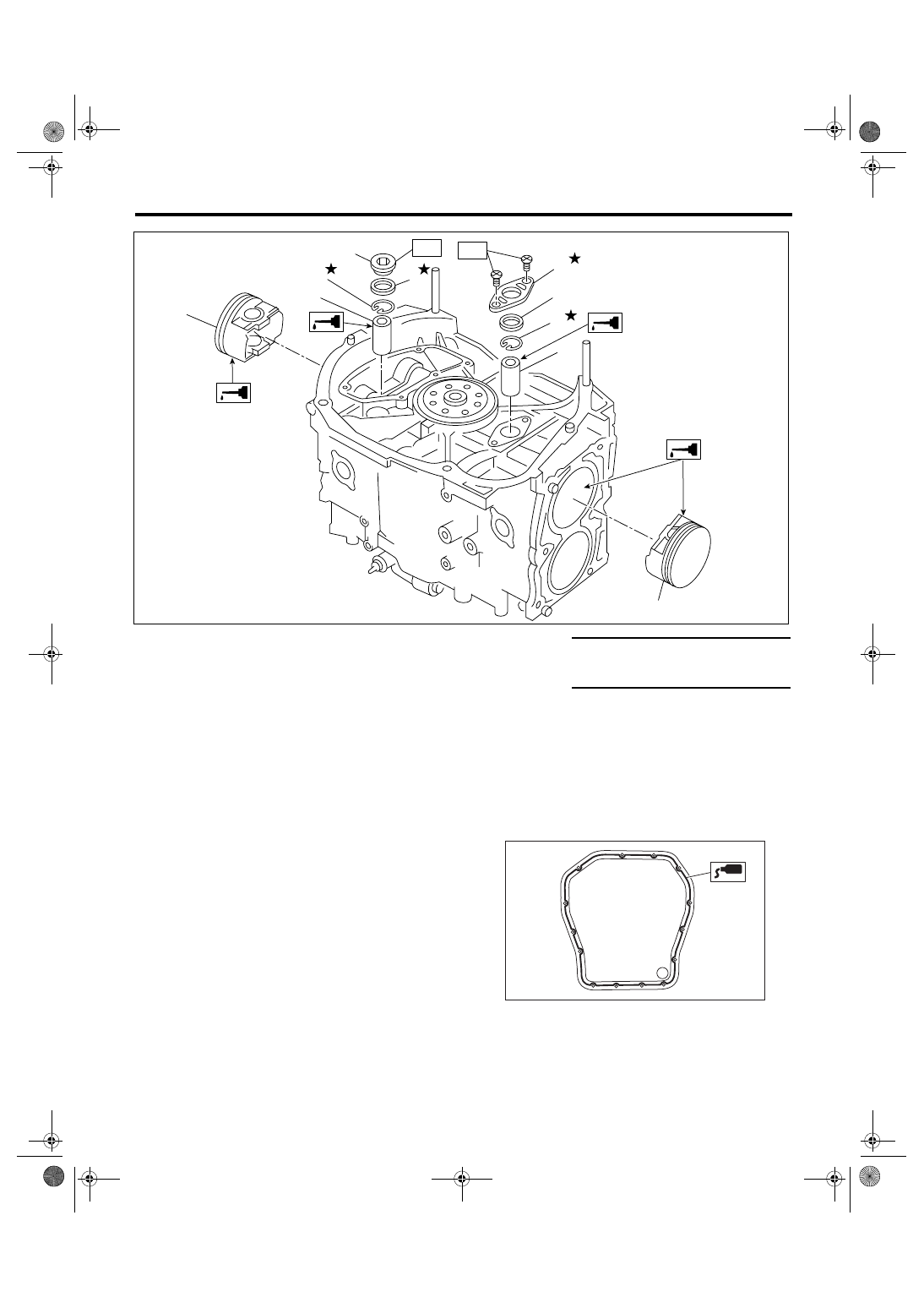
(6) Place the #3 and #4 cylinder side upward.
Following the same procedures as used for #1
and #2 cylinders, install the pistons and piston
pins.
22) Install the water pipe.
23) Install the baffle plate.
Tightening torque:
6.4 N
⋅
m (0.65 kgf-m, 4.7 ft-lb)
24) Install the oil strainer and O-ring.
Tightening torque:
10 N
⋅
m (1.0 kgf-m, 7.4 ft-lb)
25) Install the oil strainer stay.
26) Apply liquid gasket to the mating surfaces, and
install the oil pan.
Liquid gasket:
THREE BOND 1207C (Part No. 004403012) or
equivalent
Tightening torque:
5 N
⋅
m (0.5 kgf-m, 3.7 ft-lb)
(1)
Piston
(5)
Service hole plug
Tightening torque: N
⋅
m (kgf-m, ft-lb)
(2)
Piston pin
(6)
Service hole cover
T1: 6.4 (0.65, 4.7)
(3)
Snap ring
(7)
O-ring
T2: 70 (7.1, 51.6)
(4)
Gasket
(1)
(2)
(3)
(1)
(2)
(6)
(3)
(7)
(4)
(5)
ME-00161
T2
T1
ME-00162
Нет комментариевНе стесняйтесь поделиться с нами вашим ценным мнением.
Текст