Subaru Legacy (2005 year). Service manual — part 202
EN(H4SO 2.5)(diag)-93
ENGINE (DIAGNOSTICS)
Diagnostic Procedure with Diagnostic Trouble Code (DTC)
G: DTC P0103 MASS OR VOLUME AIR FLOW CIRCUIT HIGH INPUT
DTC DETECTING CONDITION:
Immediately at fault recognition
TROUBLE SYMPTOM:
• Erroneous idling
• Engine stalls.
• Poor driving performance
CAUTION:
After repair or replacement of faulty parts, conduct Clear Memory Mode <Ref. to EN(H4SO 2.5)(diag)-
40, Clear Memory Mode.> and Inspection Mode <Ref. to EN(H4SO 2.5)(diag)-33, Inspection Mode.>.
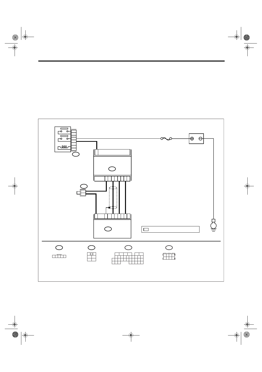
WIRING DIAGRAM:
EN-03459
B3
BATTERY
E
1
B3
MASS AIR FLOW AND
INTAKE AIR TEMPERATURE
SENSOR
ECM
B136
SBF-7
3
4
1
2
5
6
B47
2
4
3
5
31
13
23
35
32
MAIN RELAY
B47
1
2
6
3
5
1 2 3 4
5 6 7 8
B83
B136
5
6
7 8
2
1
9
4
3
10
24
22 23
25
11 12 13 14 15
26 27
28
16
17 18 19 20 21
33 34
29
32
30
31
35
*
: TERMINAL No. RANDOM ARRANGEMENT
B83
*
1 2 3 4 5
4
*

EN(H4SO 2.5)(diag)-94
ENGINE (DIAGNOSTICS)
Diagnostic Procedure with Diagnostic Trouble Code (DTC)
Step
Check
Yes
No
1
CHECK CURRENT DATA.
1) Turn the ignition switch to OFF.
2) Connect the Subaru Select Monitor or gen-
eral scan tool to data link connector.
3) Turn the ignition switch to ON, and turn the
power switch of Subaru Select Monitor or gen-
eral scan tool to ON.
4) Start the engine.
5) Read the voltage of mass air flow sensor
using Subaru Select Monitor or general scan
tool.
NOTE:
• Subaru Select Monitor
For detailed operation procedure, refer to
“READ CURRENT DATA FOR ENGINE”. <Ref.
to EN(H4SO 2.5)(diag)-25, Subaru Select
Monitor.>
• General scan tool
For detailed operation procedure, refer to the
general scan tool operation manual.
Is the voltage 0.2 — 4.7 V?
Even if the mal-
function indicator
light illuminates,
the circuit has
returned to a nor-
mal condition at
this time.
2
CHECK HARNESS BETWEEN ECM AND
MASS AIR FLOW SENSOR CONNECTOR.
1) Turn the ignition switch to OFF.
2) Disconnect the connector from mass air-
flow sensor.
3) Turn the ignition switch to ON.
4) Measure the voltage between mass air flow
sensor connector and chassis ground.
Connector & terminal
(B3) No. 3 (+) — Chassis ground (
−
):
Is the voltage more than 5 V?
Repair the battery
short circuit of har-
ness between
mass air flow sen-
sor connector and
ECM connector.
3
CHECK HARNESS BETWEEN ECM AND
MASS AIR FLOW SENSOR CONNECTOR.
1) Turn the ignition switch to OFF.
2) Disconnect the connector from ECM.
3) Measure the resistance of harness
between ECM connector and mass air flow
sensor connector.
Connector & terminal
(B3) No. 2 — (B136) No. 31:
Is the resistance less than 1
Ω?
Replace the mass
air flow sensor.
<Ref. to FU(H4SO
2.5)-26, Mass Air
Flow and Intake
Air Temperature
Sensor.>
Repair the open
circuit of harness
between mass air
flow sensor con-
nector and ECM
connector.
EN(H4SO 2.5)(diag)-95
ENGINE (DIAGNOSTICS)
Diagnostic Procedure with Diagnostic Trouble Code (DTC)
H: DTC P0107 MANIFOLD ABSOLUTE PRESSURE/BAROMETRIC PRESSURE
CIRCUIT LOW INPUT
DTC DETECTING CONDITION:
Immediately at fault recognition
CAUTION:
After repair or replacement of faulty parts, conduct Clear Memory Mode <Ref. to EN(H4SO 2.5)(diag)-
40, Clear Memory Mode.> and Inspection Mode <Ref. to EN(H4SO 2.5)(diag)-33, Inspection Mode.>.
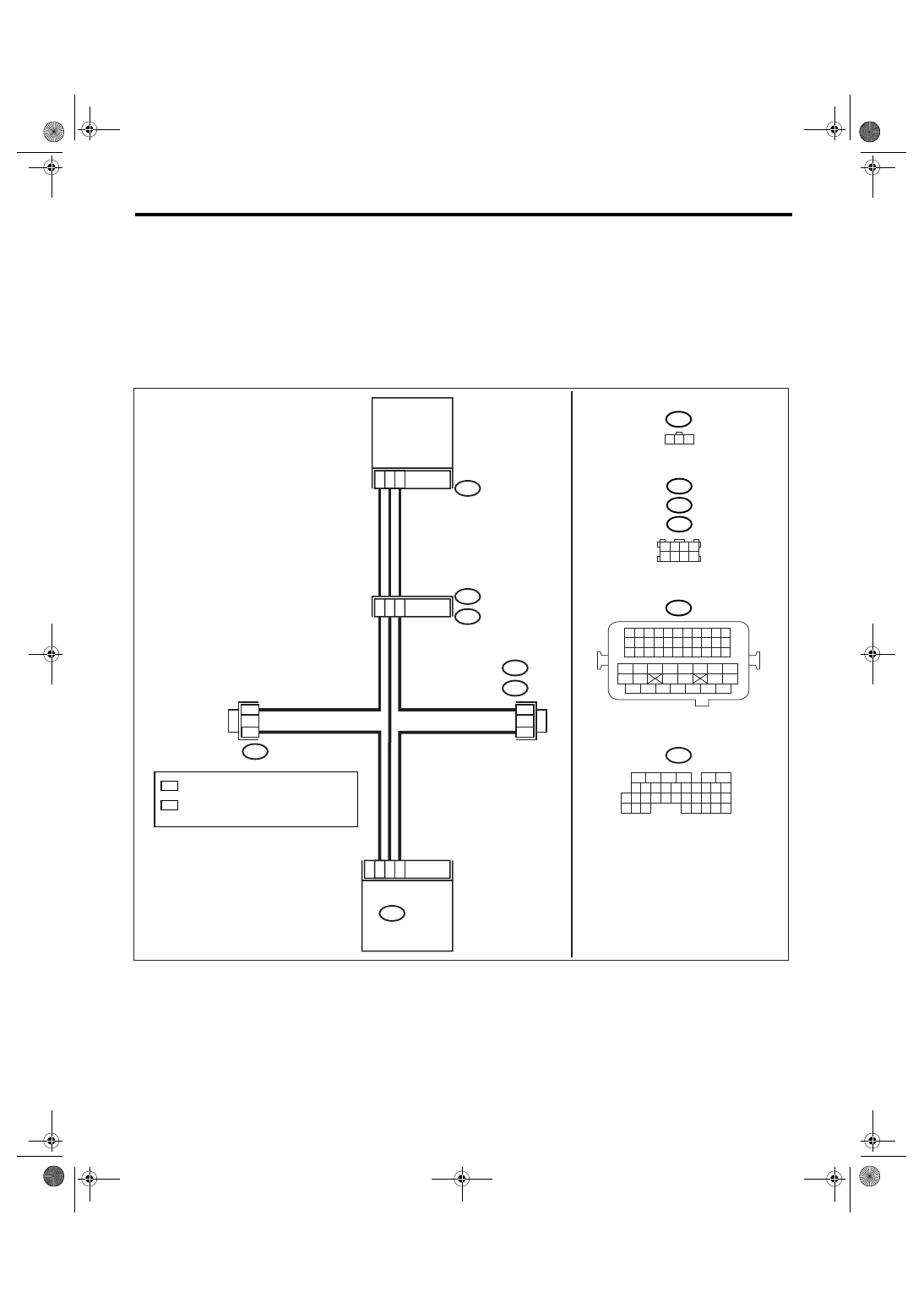
WIRING DIAGRAM:
• EC, EK, EH, ER and K4 model
• KA and KS model
NOTE:
Fuel injection system for KA and KS model is the same as 2.0 L model. Refer to EN(H4SO 2.0) section.
EN-03460
35
22
16
MANIFOLD
ABSOLUTE
PRESSURE
SENSOR
19
20
7
B21
E2
2
3
1
E21
ECM
B21
B136
2
2
1 2 3 4
5 6 7 8
B122
B138
B83
1 2 3 4
12 13 14 15
5 6 7 8
16 17 18 19
9 10 11
20 21 22
23 24 25 26 27 28 29 30 31 32 33
35
34
37
36
39
38
41
40
43
42
44
45
47
46
49
48
51
50
53
52
54
B136
5
6
7 8
2
1
9
4
3
10
24
22 23
25
11 12 13 14 15
26 27
28
16
17 18 19 20 21
33 34
29
32
30
31
35
*
: TERMINAL No. RANDOM ARRANGEMENT
E21
B122 : RHD
B138 : LHD
B83
1 2 3
*
*
1
1
1
*
: TERMINAL No. RANDOM ARRANGEMENT
AMONG 1,2,5, AND 6
2
*
*

EN(H4SO 2.5)(diag)-96
ENGINE (DIAGNOSTICS)
Diagnostic Procedure with Diagnostic Trouble Code (DTC)
Step
Check
Yes
No
1
CHECK OPTION CODE.
Is the option code EC, EK, EH,
ER or K4?
Refer to EN(H4SO
2.0) section. <Ref.
to EN(H4SO
2.0)(diag)-64, List
of Diagnostic Trou-
ble Code (DTC).>
NOTE:
Fuel injection sys-
tem for KA and KS
model is the same
as 2.0 L model.
2
CHECK CURRENT DATA.
1) Start the engine.
2) Read the data of intake manifold absolute
pressure signal using Subaru Select Monitor or
general scan tool.
NOTE:
• Subaru Select Monitor
For detailed operation procedure, refer to
“READ CURRENT DATA FOR ENGINE”. <Ref.
to EN(H4SO 2.5)(diag)-25, Subaru Select
Monitor.>
• General scan tool
For detailed operation procedure, refer to the
general scan tool operation manual.
Is the value less than 13.3 kPa
(100 mmHg, 3.94 inHg)?
3
CHECK POOR CONTACT.
Check poor contact in ECM and manifold
absolute pressure sensor connector.
Is there poor contact in ECM or
manifold absolute pressure
sensor connector?
Repair the poor
contact in ECM or
manifold absolute
pressure sensor
connector.
Even if the mal-
function indicator
light illuminates,
the circuit has
returned to a nor-
mal condition at
this time.
4
CHECK OUTPUT SIGNAL FROM ECM.
Measure the voltage between ECM connector
and chassis ground.
Connector & terminal
(B136) No. 16 (+) — Chassis ground (
−
):
Is the voltage more than 4.5 V? Go to step 6.
5
CHECK OUTPUT SIGNAL FROM ECM.
Measure the voltage between ECM connector
and chassis ground.
Connector & terminal
(B136) No. 16 (+) — Chassis ground (
−
):
Does the voltage change by
shaking the ECM harness and
connector?
Repair the poor
contact in ECM
connector.
Replace the ECM.
<Ref. to FU(H4SO
2.5)-37, Engine
Control Module
(ECM).>
6
CHECK INPUT SIGNAL OF ECM.
Measure the voltage between ECM and chas-
sis ground.
Connector & terminal
(B136) No. 22 (+) — Chassis ground (
−
):
Is the voltage less than 0.2 V? Go to step 8.
7
CHECK INPUT SIGNAL OF ECM (USING
SUBARU SELECT MONITOR).
Read the data of atmospheric absolute pres-
sure signal using Subaru Select Monitor.
NOTE:
For detailed operation procedure, refer to
“READ CURRENT DATA FOR ENGINE”. <Ref.
to EN(H4SO 2.5)(diag)-25, Subaru Select Mon-
itor.>
Is the value more than 13.3
kPa (100 mmHg, 3.94 inHg)
when shaking the ECM har-
ness and connector?
Repair the poor
contact in ECM
connector.
Нет комментариевНе стесняйтесь поделиться с нами вашим ценным мнением.
Текст