Subaru Legacy (2005 year). Service manual — part 524

4AT-77
AUTOMATIC TRANSMISSION
Warmer Cock
25.Warmer Cock
A: REMOVAL
1) Remove the air intake chamber. <Ref. to
IN(H4SO 2.0)-7, REMOVAL, Air Intake Chamber.>
2) Remove all the hoses from warmer cock.
3) Remove the warmer cock.
4) Remove the throttle body as necessary, and re-
move the bracket.
B: INSTALLATION
1) Install the bracket, and install the throttle body.
Tightening torque:
16 N
⋅
m (1.6 kgf-m, 11.6 ft-lb)
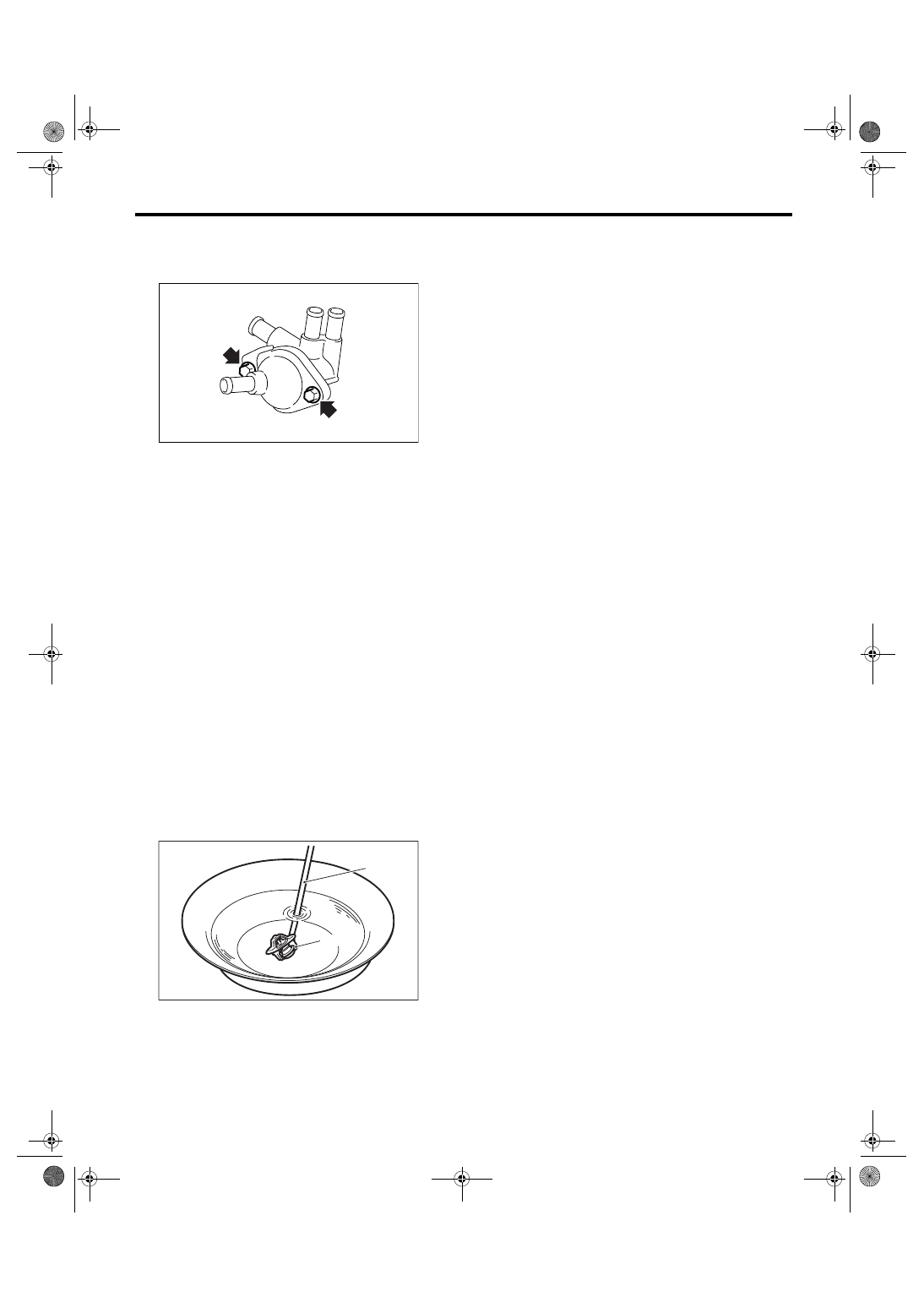
2) Install the warmer cock.
Tightening torque:
T1: 6.4 N
⋅
m (0.65 kgf-m, 4.7 ft-lb)
T2: 15 N
⋅
m (1.5 kgf-m, 10.8 ft-lb)
3) Connect the hoses to warmer cock.
4) Install the air intake chamber.
<Ref. to IN(H4SO 2.0)-7, INSTALLATION, Air In-
take Chamber.>
AT-02163
AT-02165
AT-02166
AT-02166
AT-02168
T1
T2
AT-02163
4AT-78
AUTOMATIC TRANSMISSION
Warmer Cock
C: DISASSEMBLY
Remove the bolt of warmer cock, and remove the
thermostat.
D: ASSEMBLY
Assemble in the reverse order.
Tightening torque:
6.4 N
⋅
m (0.65 kgf-m, 4.7 ft-lb)
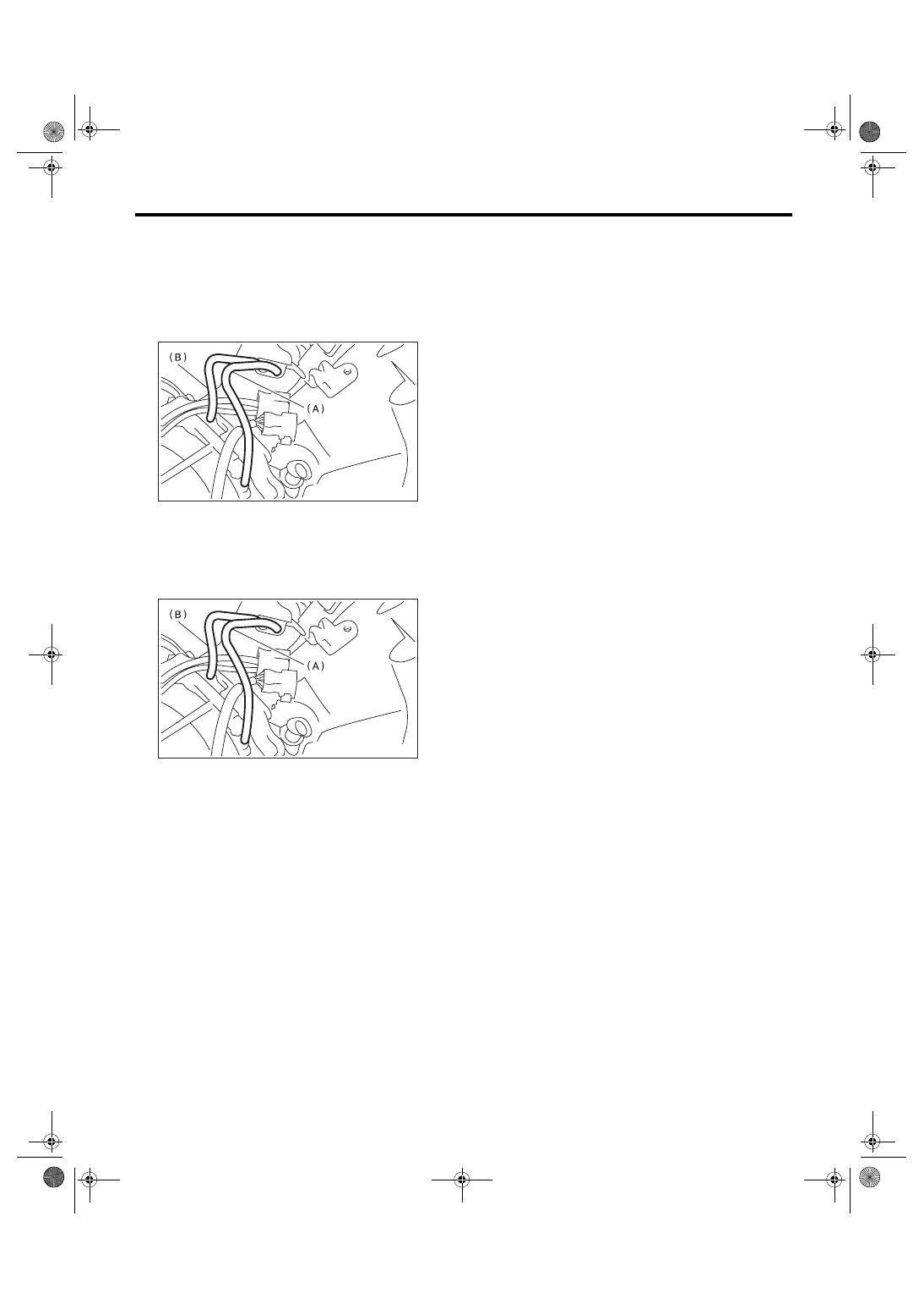
E: INSPECTION
Replace the thermostat if the valve does not close
completely at an ambient temperature or if the fol-
lowing test shows unsatisfactory results.
• Inspection method
Immerse the thermostat and a thermometer in wa-
ter. Raise water temperature gradually, and mea-
sure the temperature and valve lift when the valve
begins to open and when the valve is fully opened.
During the test, agitate the water for even temper-
ature distribution. The measured value should
meet the specification.
Starting temperature to open:
69 — 73
°
C (156 — 163
°
F)
Fully opens:
84
°
C (183
°
F)
Valve lift:
9.0 mm (0.354 in) or more
(A) Thermometer
(B) Thermostat
AT-02177
CO-00033
( A )
( B )
4AT-79
AUTOMATIC TRANSMISSION
Air Breather Hose
26.Air Breather Hose
A: REMOVAL
1) Remove the air intake chamber.
<Ref. to IN(H4SO 2.0)-7, REMOVAL, Air Intake
Chamber.>
2) Disconnect the air breather hose.
B: INSTALLATION
1) Install the air breather hose.
2) Install the air intake chamber.
<Ref. to IN(H4SO 2.0)-7, INSTALLATION, Air In-
take Chamber.>
C: INSPECTION
Make sure the hose is not cracked or clogged.
(A) Air breather hose (Transmission case)
(B) Air breather hose (Oil pump housing)
(A) Air breather hose (Transmission case)
(B) Air breather hose (Oil pump housing)
AT-00099
AT-00099
4AT-80
AUTOMATIC TRANSMISSION
Oil Charge Pipe
27.Oil Charge Pipe
A: REMOVAL
1) Remove the air intake chamber.
<Ref. to IN(H4SO 2.0)-7, REMOVAL, Air Intake
Chamber.>
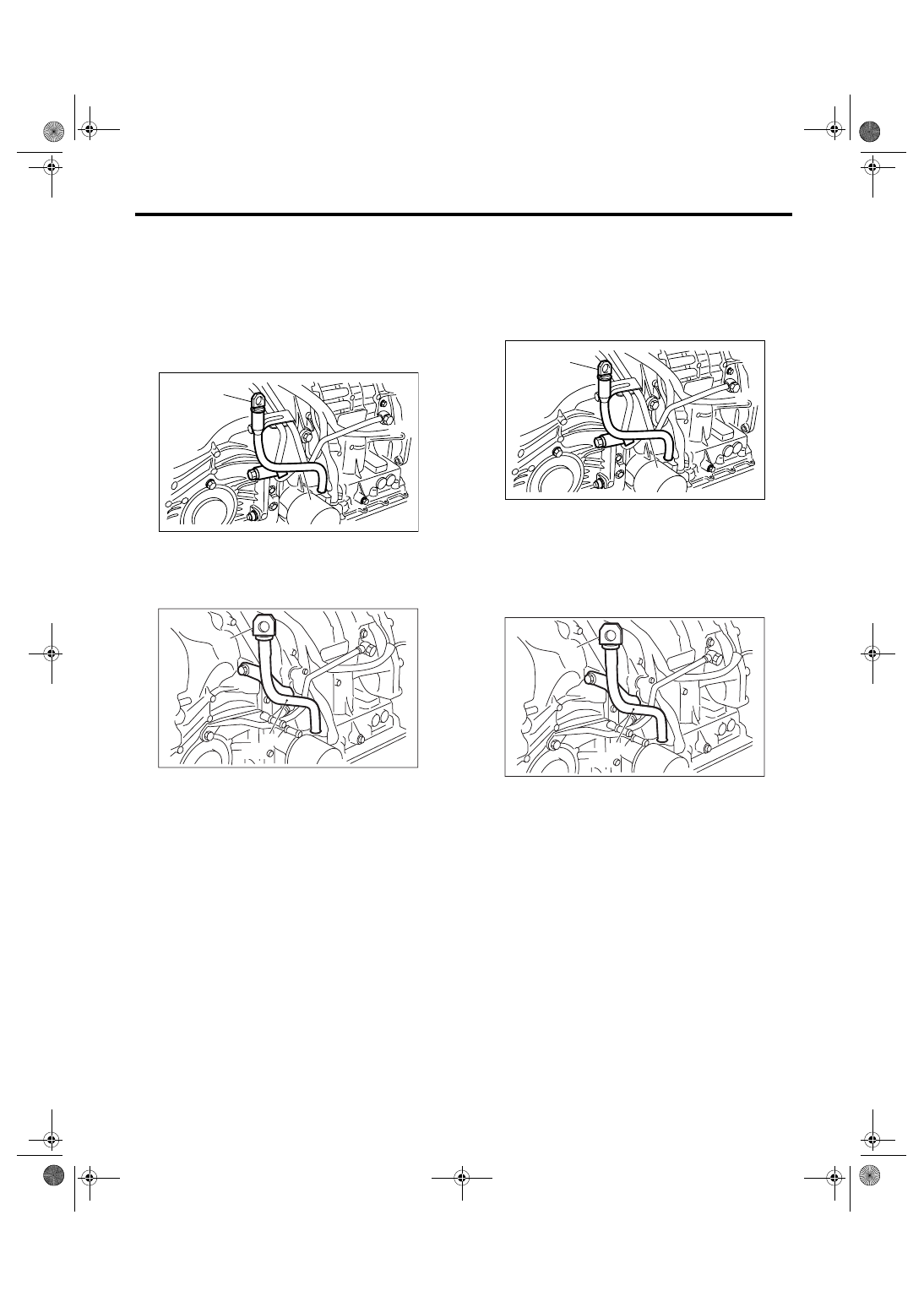
2) Remove the oil charge pipe, and then remove
the O-ring from flange side.
• Model with ATF cooler with warmer function
• Model without ATF cooler with warmer function
B: INSTALLATION
1) Install the oil charge pipe with a new O-ring ap-
plied with ATF.
• Model with ATF cooler with warmer function
Tightening torque:
41 N
⋅
m (4.2 kgf-m, 30.4 ft-lb)
• Model without ATF cooler with warmer function
Tightening torque:
41 N
⋅
m (4.2 kgf-m, 30.4 ft-lb)
2) Install the air intake chamber.
<Ref. to IN(H4SO 2.0)-7, INSTALLATION, Air In-
take Chamber.>
C: INSPECTION
Make sure the oil charge pipe is not deformed or
damaged.
(A) Oil level gauge
(B) Oil charge pipe
(A) Oil level gauge
(B) Oil charge pipe
(A)
(B)
AT-02178
AT-03202
(A)
(B)
(A) Oil level gauge
(B) Oil charge pipe
(A) Oil level gauge
(B) Oil charge pipe
(A)
(B)
AT-02178
AT-03202
(A)
(B)
Нет комментариевНе стесняйтесь поделиться с нами вашим ценным мнением.
Текст