Subaru Legacy (2005 year). Service manual — part 824
BR-25
BRAKE
Rear Brake Pad
5. Rear Brake Pad
A: REMOVAL
1) Lift-up the vehicle, and then remove the rear
wheels.
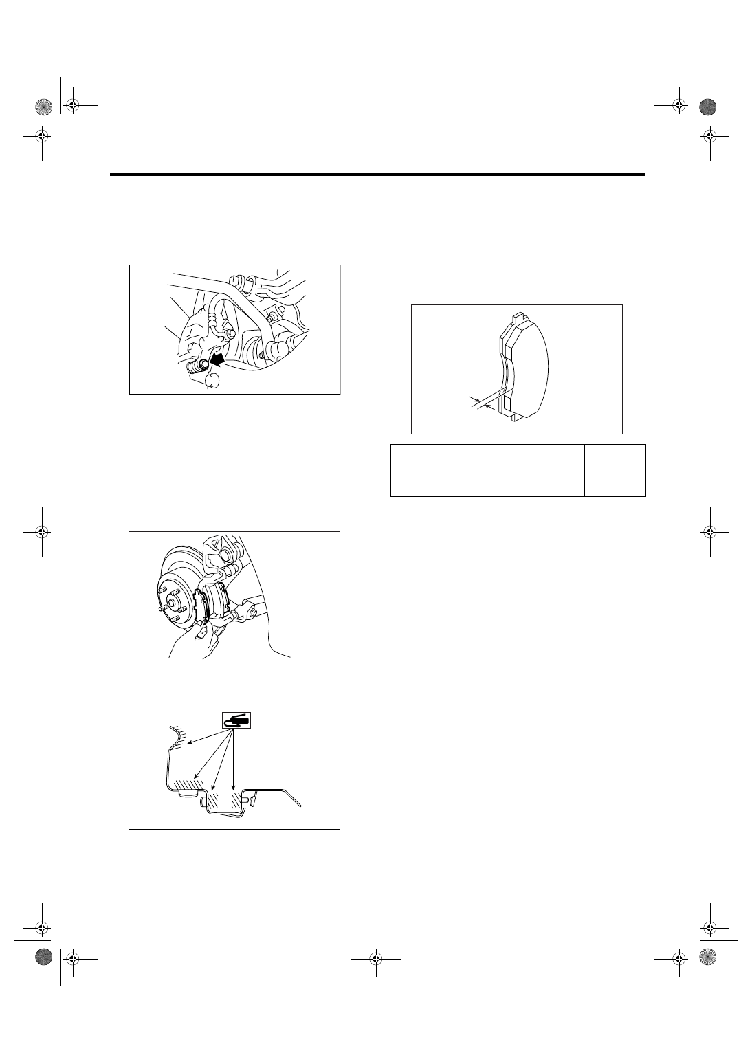
2) Remove the caliper bolt.
3) Raise the caliper body and support it.
NOTE:
Do not disconnect the brake hose from caliper
body.
4) Remove the pad.
NOTE:
If the brake pad is difficult to remove, use the same
procedure as for front disc brake pad.
<Ref. to BR-16, REMOVAL, Front Brake Pad.>
B: INSTALLATION
1) Apply a thin coat of Molykote M7439 to pad clip.
2) Apply a thin coat of Molykote AS880N (Part No.
K0777YA010) to the frictional portion between pad
and shim.
3) Install the pad on support.
4) Install the caliper body on support.
Tightening torque:
Solid disc brake model
27 N
⋅
m (2.8 kgf-m, 19.9 ft-lb)
Ventilated disc brake model
37 N
⋅
m (3.8 kgf-m, 27.3 ft-lb)
C: INSPECTION
Check the pad thickness A.
NOTE:
• Always replace the pads for both wheels LH and
RH as a set.
• Also replace pad clips if they are twisted or worn.
• A wear indicator is provided on the inner disc
brake pad. If the pad wears down to such an extent
that the end of wear indicator contacts disc rotor, a
squeaking sound is produced as the wheel rotates.
If this sound is heard, replace the pad.
• Replace the pad if there is oil or grease on it.
BR-00344
BR-00032
BR-00345
Type of disc rotor
Solid
Ventilated
Pad thickness
Specifica-
tion
9.0 (0.35)
9.0 (0.35)
mm (in) Wear limit
1.5 (0.059)
1.5 (0.059)
A
BR-00016
BR-26
BRAKE
Rear Disc Rotor
6. Rear Disc Rotor
A: REMOVAL
1) Lift-up the vehicle, and then remove the rear
wheels.
2) Release the parking brake.
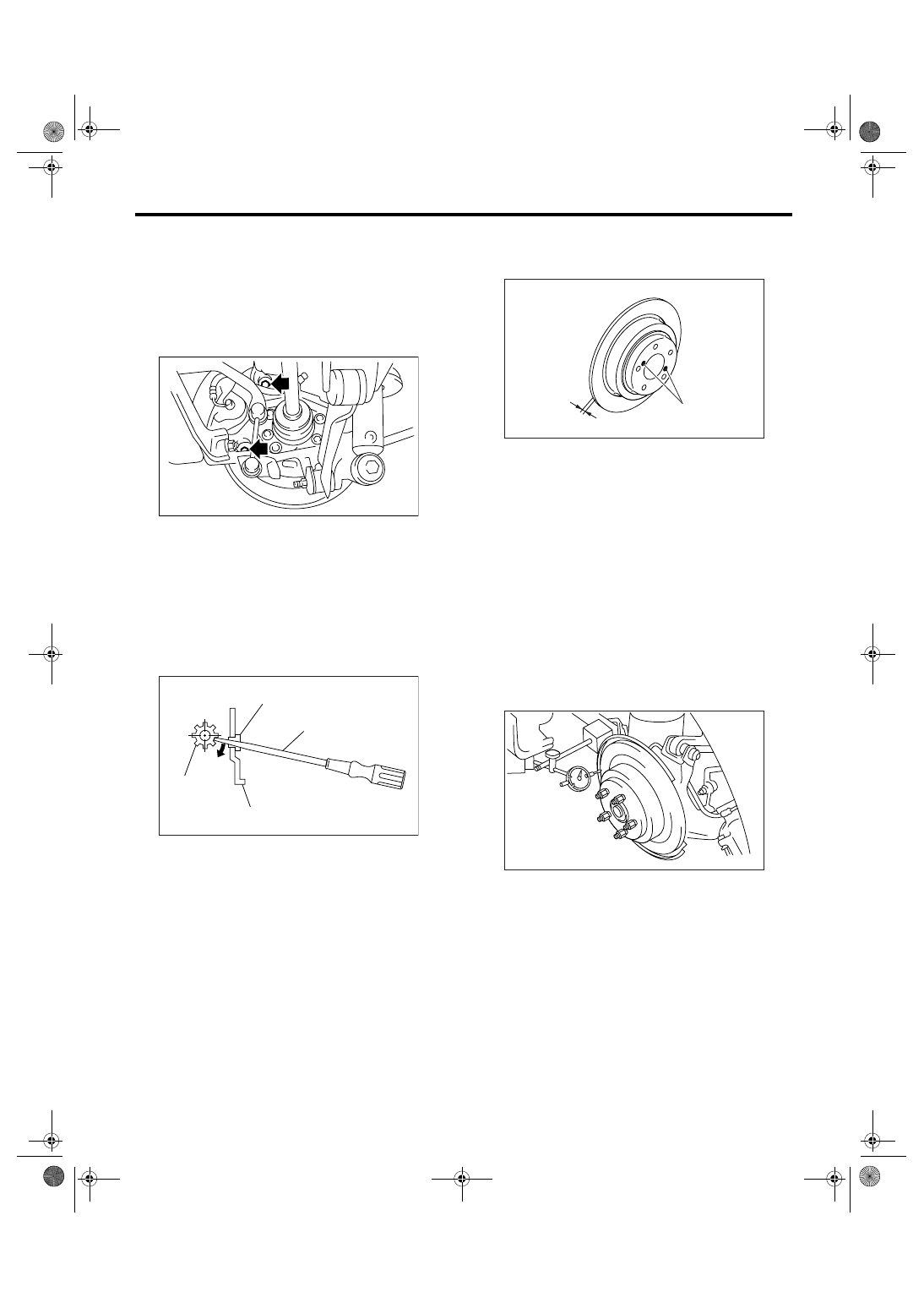
3) Remove the two mounting bolts, and remove the
disc brake assembly.
4) Suspend the disc brake assembly so that the
hose is not stretched.
5) Remove the disc rotor.
NOTE:
If the disc rotor is difficult to remove, try following
two methods in order.
(1) Turn the adjusting screw using a flat tip
screwdriver until the brake shoe gets away
enough from the disc rotor.
(2) If the disc rotor seizes up within hub, drive
the disc rotor out by pushing with an 8 mm bolt in
holes B on the rotor.
B: INSTALLATION
1) Install in the reverse order of removal.
2) Adjust the parking brake. <Ref. to PB-8, AD-
JUSTMENT, Parking Brake Assembly (Rear Disc
Brake).>
C: INSPECTION
1) Check rear wheel bearing play and axial hub
runout before disc rotor runout limit inspection.
<Ref. to DS-21, INSPECTION, Rear Hub Unit
Bearing.>
2) Secure the disc rotor by tightening five wheel
nuts.
3) Set a dial gauge 10 mm (0.39 in) inward of disc
rotor outer perimeter. Turn the disc rotor to check
runout. If the disc rotor runout exceeds limit, re-
place with a new disc rotor.
Disc rotor runout limit:
0.05 mm (0.0020 in)
(1) Adjusting screw
(2) Cover
(3) Flat tip screwdriver
(4) Back plate
BR-00346
(1)
(4)
(2)
(3)
BR-00155
A
B
BR-00036
BR-00037
BR-27
BRAKE
Rear Disc Rotor
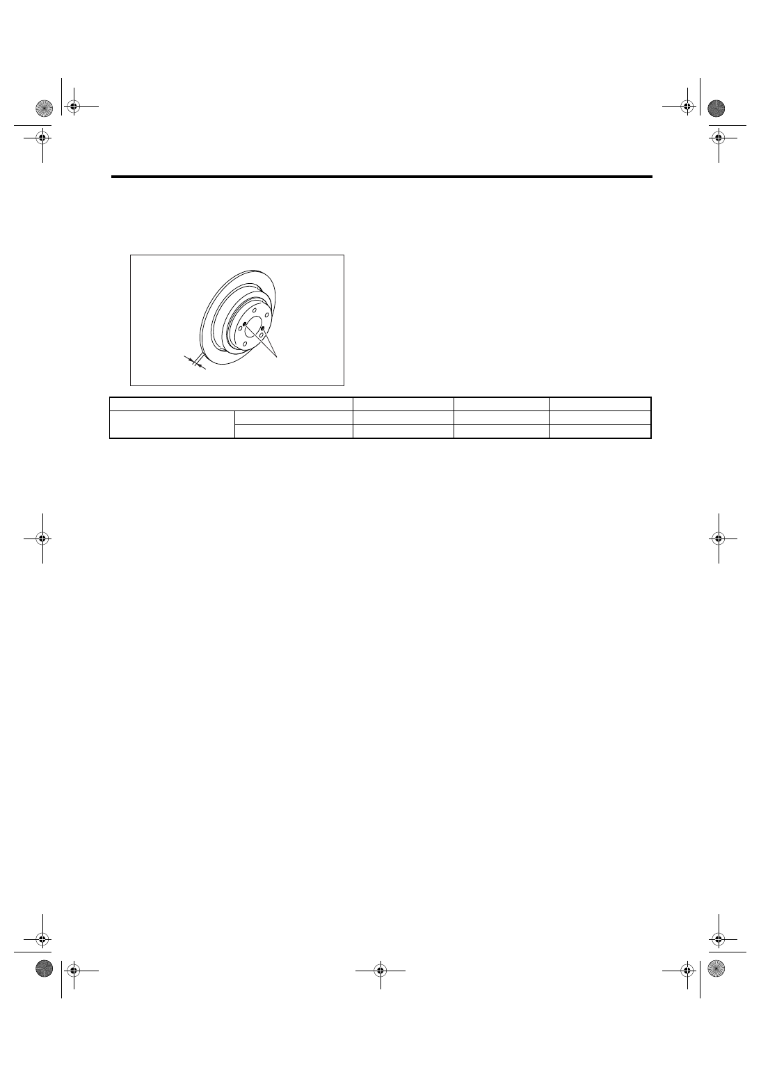
4) Set a micrometer 10 mm (0.39 in) inward of the
disc rotor outer perimeter, and then measure the
disc rotor thickness. If the thickness of disc rotor
exceeds the service limit, replace with a new disc
rotor.
A
B
BR-00036
Specification
Limit
Disc outer dia.
Disc rotor thickness A
Solid disc
10 (0.39)
8.5 (0.335)
274 (10.79)
mm (in) Ventilated disc
18 (0.71)
16 (0.63)
290 (11.42)
BR-28
BRAKE
Rear Disc Brake Assembly
7. Rear Disc Brake Assembly
A: REMOVAL
CAUTION:
Do not allow brake fluid to come in contact with
vehicle body; wash away with water and wipe
off completely if spilled.
1) Lift-up the vehicle, and then remove the rear
wheels.
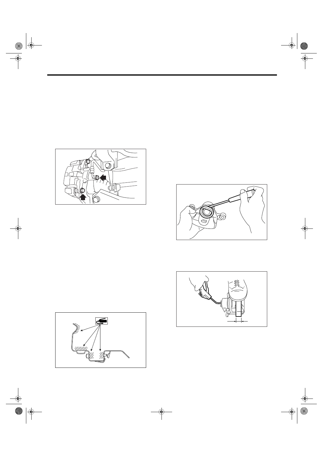
2) Disconnect the brake hose from caliper body as-
sembly.
3) Remove the caliper lower bolts.
4) Raise the caliper body, and then move it toward
vehicle center to separate it from the support.
5) Remove the support from housing.
NOTE:
Remove the support only when replacing itself or
rotor. It need not be removed when servicing the
caliper body assembly.
6) Clean mud and foreign particles from the caliper
body assembly and the support.
CAUTION:
Be careful not to allow foreign particles to enter
the brake hose connector.
B: INSTALLATION
1) Install the support on housing.
Tightening torque:
53 N
⋅
m (5.4 kgf-m, 39.1 ft-lb)
2) Apply a thin coat of Molykote M7439 to pad clip.
3) Apply a thin coat of Molykote AS880N (Part No.
K0777YA010) to the frictional portion between pad
and shim.
4) Install the pad on support.
5) Install the caliper body on support.
Tightening torque:
Solid disc brake model
27 N
⋅
m (2.8 kgf-m, 19.9 ft-lb)
Ventilated disc brake model
37 N
⋅
m (3.8 kgf-m, 27.3 ft-lb)
6) Connect the brake hose using new brake hose
gaskets.
Tightening torque:
18 N
⋅
m (1.8 kgf-m, 13.0 ft-lb)
7) Bleed air from the brake system.
C: DISASSEMBLY
1) Remove the piston boot.
2) Place a wooden block in caliper body as shown
in the figure to prevent the piston from jumping out
and avoid being damaged.
3) Gradually supply compressed air via installation
hole of brake hose to force the piston out.
BR-00347
BR-00345
(1) Place a 30 mm (1.18 in) wide wooden block
here.
BR-00041
(1)
BR-00042
Нет комментариевНе стесняйтесь поделиться с нами вашим ценным мнением.
Текст