Subaru Legacy (2005 year). Service manual — part 628
5AT(diag)-103
AUTOMATIC TRANSMISSION (DIAGNOSTICS)
Diagnostic Procedure with Diagnostic Trouble Code (DTC)
7
CHECK INPUT SIGNAL FOR TCM USING
SUBARU SELECT MONITOR.
1) Connect all the connectors.
2) Jack-up the vehicle and support with rigid
racks.
NOTE:
Raise all wheels off floor.
3) Start the engine, and drive the vehicle.
4) Read the current data of front wheel speed
using Subaru Select Monitor.
<Ref. to 5AT(diag)-17, OPERATION, Subaru
Select Monitor.>
NOTE:
The speed difference between front and rear
wheels may light the ABS warning light, but this
indicates no malfunction. When AT control di-
agnosis is finished, perform the ABS memory
clearance procedure of on-board diagnostics
system. <Ref. to ABS(diag)-26, Clear Memory
Mode.>
Does the value of the front
wheel speed depending on the
acceleration and deceleration
of the vehicle?
Even if the SPORT
indicator lights
blinks, the system
is in normal condi-
tion. A temporary
poor contact of
connector or har-
ness may be the
cause. Repair poor
contact of har-
ness in ATF tem-
perature sensor
and transmission
connector.
Replace the trans-
mission harness.
Step
Check
Yes
No
5AT(diag)-104
AUTOMATIC TRANSMISSION (DIAGNOSTICS)
Diagnostic Procedure with Diagnostic Trouble Code (DTC)
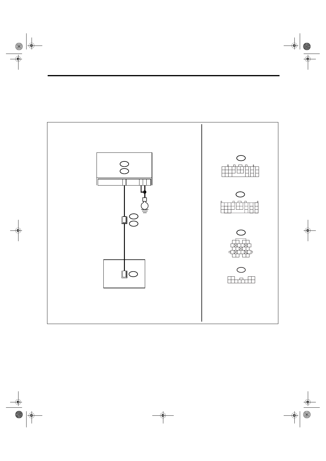
AI: DTC P1707 AT AWD SOLENOID VALVE CIRCUIT MALFUNCTION
DTC DETECTING CONDITION:
Output signal circuit of transfer solenoid is open or shorted.
TROUBLE SYMPTOM:
• Tight corner braking phenomenon is occurred.
• Drivability getting worse.
WIRING DIAGRAM:
AT-03194
A5
A14
E
B23
B11
B54
B11
1 2
5
6 7
8
13
14 15
16
9 10
11 12
3 4
17 18
19 20
TRANSMISSION
1 2
7
8
9
5 6
3 4
10 11 12
19 20 21
13
14 15
16
17
18
22
23
24
T4
11
T11
1 2
5
8
6
9 10 11
3 4
12
T11
7
8
1 2 3 4
10 11 12
19 20 21
13
5 6
14 15
7
8
9
16
17
18
22
23
24
B55
B:
A:
B54
B55
A:
B:
TCM
5AT(diag)-105
AUTOMATIC TRANSMISSION (DIAGNOSTICS)
Diagnostic Procedure with Diagnostic Trouble Code (DTC)
Step
Check
Yes
No
1
CHECK HARNESS CONNECTOR BETWEEN
TCM AND TRANSMISSION.
1) Turn the ignition switch to OFF.
2) Disconnect the connectors from TCM and
transmission.
3) Measure the resistance of harness
between TCM and transmission connector.
Connector & terminal
(B55) No. 23 — (B11) No. 8:
(B54) No. 5 — Chassis ground:
(B54) No. 14 — Chassis ground:
Is the resistance less than 1
Ω?
Repair the open
circuit of harness
between TCM con-
nector and trans-
mission connector.
2
CHECK HARNESS CONNECTOR BETWEEN
TCM AND CHASSIS GROUND.
Measure the resistance of harness between
TCM connector and chassis ground.
Connector & terminal
(B55) No. 23 — Chassis ground:
Is the resistance more than 1
M
Ω?
Repair the short
circuit of harness
between TCM con-
nector and trans-
mission connector.
3
CHECK HARNESS CONNECTOR BETWEEN
TRANSMISSION AND CONTROL VALVE
BODY.
1) Turn the ignition switch to OFF.
2) Disconnect the connector from transmis-
sion.
3) Remove the transmission connector from
bracket.
4) Jack-up the vehicle and place it on rigid
racks.
NOTE:
Raise all wheels off floor.
5) Drain the ATF.
CAUTION:
Do not drain the ATF until it cools down.
6) Remove the oil pan, and disconnect the
control valve body connector.
7) Measure the resistance between transmis-
sion connector and control valve body connec-
tor.
Connector & terminal
(T4) No. 8 — (T11) No. 11:
Is the resistance less than 1
Ω?
Repair the open
circuit of harness
between control
valve body con-
nector and trans-
mission connector.
4
CHECK HARNESS CONNECTOR BETWEEN
TRANSMISSION AND CONTROL VALVE
BODY.
Measure the resistance between transmission
ground and control valve body connector.
Connector & terminal
(T11) No. 11 — Transmission ground:
Is the resistance more than 1
M
Ω?
Repair the short
circuit of harness
between control
valve body con-
nector and trans-
mission ground.
5
CHECK AWD SOLENOID.
Measure the resistance between transmission
ground and control valve body connector.
Connector & terminal
(T11) No. 11 — Transmission ground:
Is the resistance 3 — 9
Ω
Replace the con-
trol valve body.
<Ref. to 5AT-58,
Control Valve
Body.>
6
CHECK POOR CONTACT.
Check that there are no poor contact in TCM
connector, transmission connector and control
valve body connector.
Is there any loosing terminal,
entering foreign matter, dam-
aging connector body?
Repair the poor
contact.
5AT(diag)-106
AUTOMATIC TRANSMISSION (DIAGNOSTICS)
Diagnostic Procedure with Diagnostic Trouble Code (DTC)
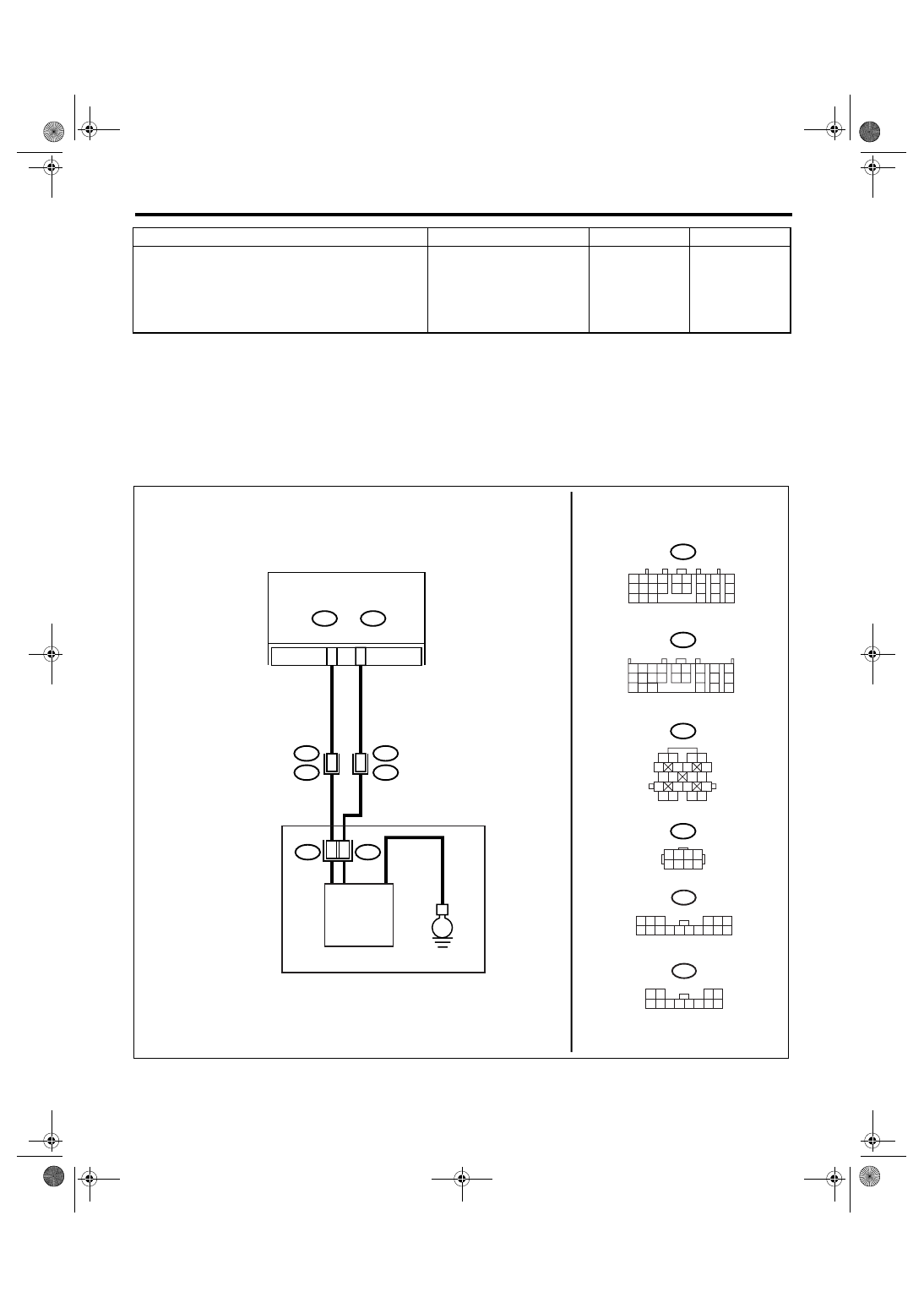
AJ:DTC P1710 TORQUE CONVERTER TURBINE 2 SPEED SIGNAL CIRCUIT 2
MALFUNCTION
DTC DETECTING CONDITION:
Input signal circuit of TCM is open or shorted.
TROUBLE SYMPTOM:
• Excessive shift shock
• Does not shift to 5th
WIRING DIAGRAM:
7
CHECK AFTER REPAIR.
1) Perform the clear memory mode.
2) Drive for a while, read the DTC, and verify
that there is no faulty.
Is DTC displayed?
Replace the TCM.
<Ref. to 5AT-61,
Transmission Con-
trol Module
(TCM).>
Temporary poor
contact or open
circuit occurs.
Recheck that the
harness connec-
tor has no faulty.
Step
Check
Yes
No
AT-03195
1 2 3 4
10 11 12
19 20 21
13
5 6
14 15
7
8
9
16
17
18
22
23
24
1 2 3 4
5 6 7 8
B54
B55
1 2
7
8
9
5 6
3 4
10 11 12
19 20 21
13
14 15
16
17
18
22
23
24
B11
B12
1 2
5
6 7
8
13
14 15
16
9 10
11 12
3 4
17 18
19 20
B54
A:
B55
B:
A16
7
B11
T4
B12
T3
TCM
TURBINE SPEED SENSOR 2
TRANSMISSION
B22
6
E
B:
A:
15
3
T10
T11
1 2 3
6
8 9 10 11 12 13 14
4 5
15 16
T10
7
1 2
5
8
6
9 10 11
3 4
12
T11
7
Нет комментариевНе стесняйтесь поделиться с нами вашим ценным мнением.
Текст