Subaru Legacy (2005 year). Service manual — part 929
LI-13
LIGHTING SYSTEM
Combination Base Switch Assembly
11.Combination Base Switch
Assembly
A: REMOVAL
1) Remove the driver’s airbag module. <Ref. to AB-
16, REMOVAL, Driver’s Airbag Module.>
2) Remove the steering wheel. <Ref. to PS-21, RE-
MOVAL, Steering Wheel.>
3) Remove the screws and remove the steering
column lower cover.
4) Remove the combination switch. <Ref. to LI-10,
REMOVAL, Combination Switch (Light).> <Ref. to
WW-8, REMOVAL, Combination Switch (Wiper).>
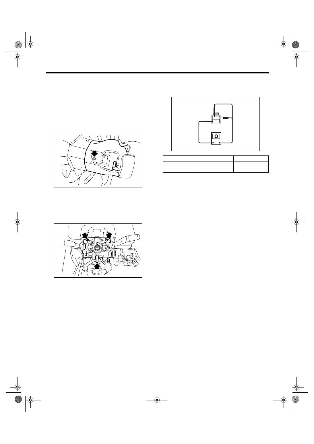
5) Remove the four screws and remove the roll
connector.
6) Remove the three screws.
7) Disconnect the connector and remove the com-
bination base switch assembly.
B: INSTALLATION
1) Install in the reverse order of removal.
2) Before installing steering wheel, be sure the di-
rection of roll connector is adjusted with steering.
<Ref. to AB-25, ADJUSTMENT, Roll Connector.>
C: INSPECTION
1. COMBINATION BASE SWITCH ASSEM-
BLY
Inspect the combination base switch assembly and
roll connector for crack or deformation. If any dam-
age is found, replace with a new one.
2. PARKING SWITCH
Measure the resistance between parking switch
terminals.
SL-00258
LI-00271
Switch position
Terminal No.
Standard
OFF
2 and 4
Less than 1
Ω
ON
1 and 4
Less than 1
Ω
LI-00183
1
2
3
4
LI-14
LIGHTING SYSTEM
Headlight Assembly
12.Headlight Assembly
A: REMOVAL
1) Disconnect the ground cable from battery.
2) Remove the air intake duct. (When removing the
headlight RH)
3) Remove the front grille. <Ref. to EI-24, REMOV-
AL, Front Grille.>
4) Remove the front bumper. <Ref. to EI-30, RE-
MOVAL, Front Bumper.>
5) Disconnect each harness connector.
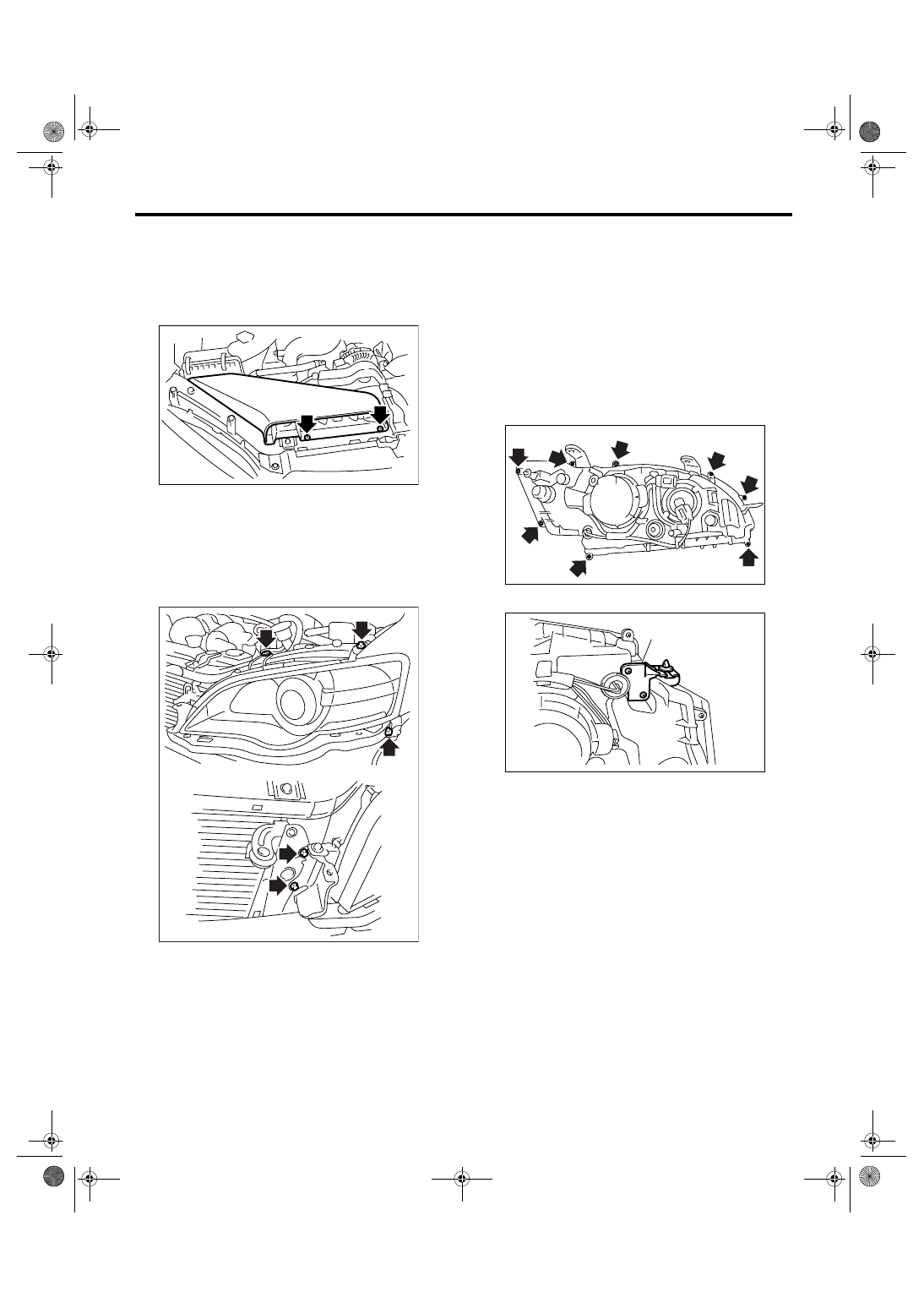
6) Remove the four bolts and disengage clips, and
then detach the headlight assembly.
B: INSTALLATION
Install in the reverse order of removal.
C: DISASSEMBLY
CAUTION:
• Do not touch the bulb glass portion.
• Do not touch inside the lens (extension por-
tion) or reflector portion.
• Replace the packing with a new one.
1) Remove the headlight assembly. <Ref. to LI-14,
REMOVAL, Headlight Assembly.>
2) Remove the eight screws.
3) Remove headlight side bracket.
LI-00273
LI-00274
(A) Headlight side bracket
LI-00327
LI-00328
(A)
LI-15
LIGHTING SYSTEM
Headlight Assembly
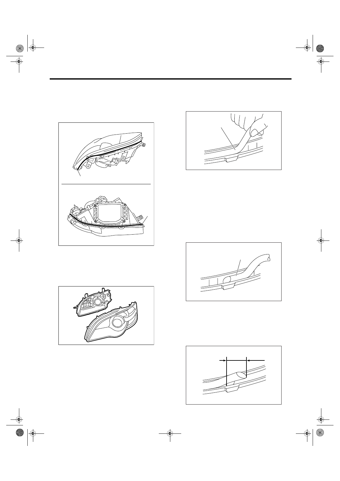
4) Heat the sealing portion between headlight as-
sembly and lens using heating gun.
CAUTION:
Avoid heating one specific point of the seal por-
tion and heating the headlight assembly to
100
°C (212°F) or more.
5) Unhook the hook, and then take the lens off the
headlight assembly.
6) Remove the packing (A) from seal groove.
CAUTION:
Completely remove the packing not to leave
any chips behind.
D: ASSEMBLY
1) Cut the tip of packing (A) at an angle of 45
°.
2) With the cut end facing upward, insert packing
(A) into the groove around the seal.
CAUTION:
• If the packing protrudes, slowly take it off the
groove.
• Do not stretch the packing. If the packing is
stretched, seal fails.
3) After making a round of the seal, cut its tip at an
angle of 45
°, with its length 10 mm (0.39 in) longer
than the circumference of seal so that the tip over-
laps the other. Then, press it onto the seal, using a
screwdriver.
(A) Headlight ASSY upper
(B) Headlight ASSY lower
(C) Heated portion
(B)
(A)
(C)
(C)
LI-00329
LI-00330
(A) Packing
(A) Packing
LI-00060
(A)
LI-00061
(A)
LI-00062
10mm
LI-16
LIGHTING SYSTEM
Headlight Assembly
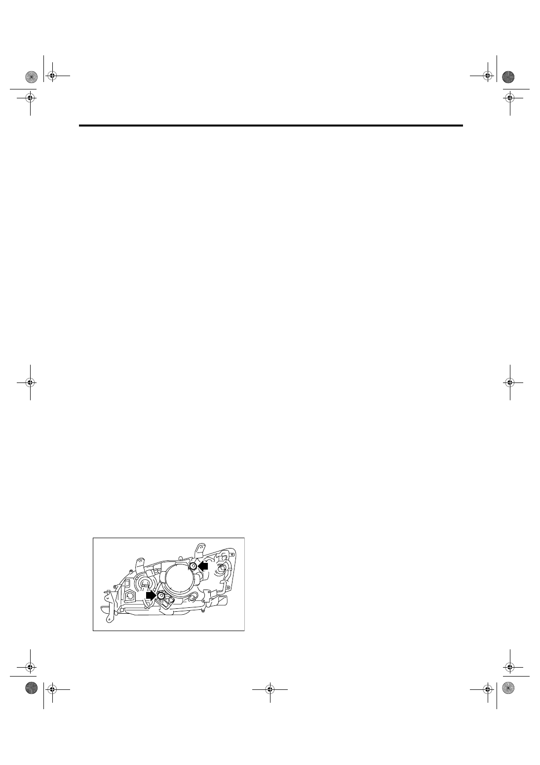
4) Match the positions of the lens and headlight as-
sembly, and then insert the lens into the headlight
assembly.
CAUTION:
Remove the turn signal light bulb and clear-
ance/parking light bulb before installing the
lens.
5) Secure the hook, and then install the clip and
screw.
6) Put the seal portion of headlight assembly into
the water and check that water does not enter in-
side the headlight.
CAUTION:
Be sure that water does not enter inside the
headlight through the bulb socket and ventila-
tion hole.
E: ADJUSTMENT
1. HEADLIGHT AIMING
CAUTION:
Turn off the light before adjusting headlight
beam level. If the light is necessary to check
aiming, do not turn on for more than two min-
utes.
NOTE:
Before checking the headlight beam level, be sure
of the following:
• The area around the headlight has not sustained
any accident, damage or other type of deformation.
• Vehicle is parked on a level surface.
• The inflation pressure of tires is correct.
• Vehicle’s fuel tank is fully filled.
1) Bounce the vehicle several times to normalize
the suspension.
2) Make certain that someone is seated in the driv-
er’s seat.
3) Turn the headlights on and then adjust the low
beam pattern.
NOTE:
• Position the headlight beam leveler switch to “0”.
• Adjust the vertical aim (A) first, then horizontal
aim (B).
LI-00275
(A)
(B)
Нет комментариевНе стесняйтесь поделиться с нами вашим ценным мнением.
Текст