Subaru Legacy (2005 year). Service manual — part 401
ME(H6DO)-79
MECHANICAL
Oil Flow Control Solenoid Valve
22.Oil Flow Control Solenoid
Valve
A: REMOVAL
Oil flow control solenoid valve is a unit with cam-
shaft cap.
Refer to “Camshaft” for removal. <Ref. to
ME(H6DO)-56, REMOVAL, Camshaft.>
B: INSTALLATION
Install in the reverse order of removal.
ME(H6DO)-80
MECHANICAL
Oil Switching Solenoid Valve
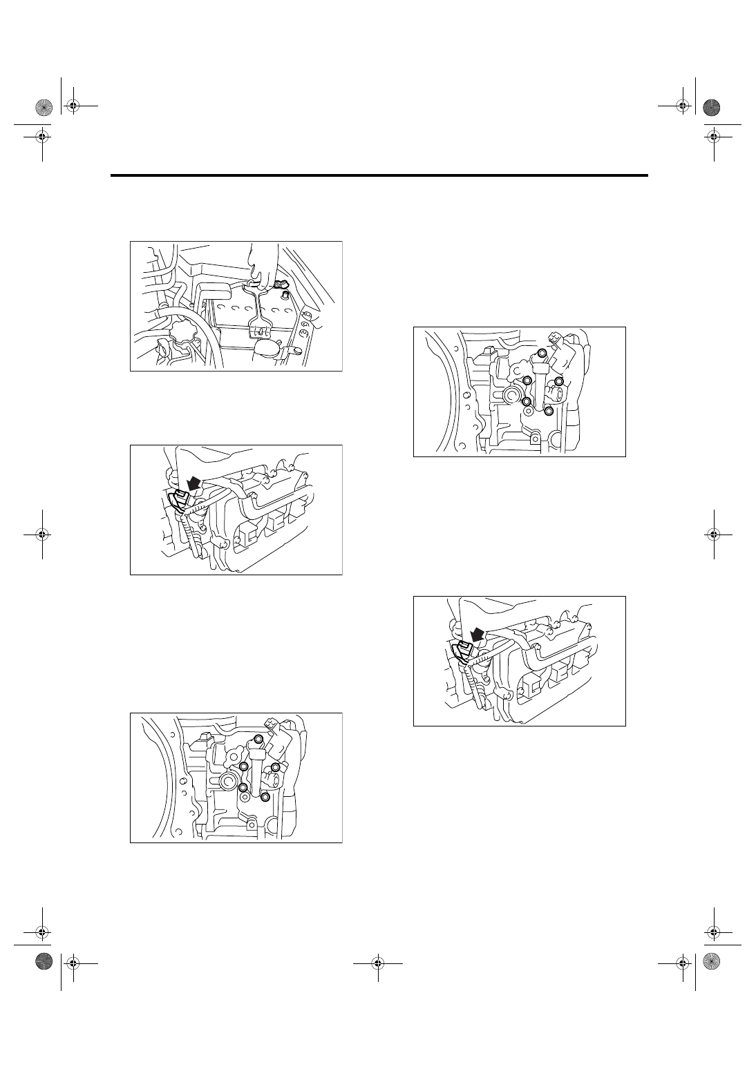
23.Oil Switching Solenoid Valve
A: REMOVAL
1) Disconnect the ground cable from battery.
2) Remove the air intake chamber.
<Ref. to IN(H6DO)-7, REMOVAL, Air Intake Cham-
ber.>
3) Disconnect the connector from oil switching so-
lenoid valve.
4) Remove the oil switching solenoid valve.
5) Remove the variable valve lift diagnosis oil pres-
sure switch.
<Ref. to FU(H6DO)-28, REMOVAL, Variable Valve
Lift Diagnosis Oil Pressure Switch.>
6) Remove the oil temperature sensor.
<Ref. to FU(H6DO)-29, REMOVAL, Oil Tempera-
ture Sensor.>
7) Remove the oil flow control solenoid valve hold-
er from cylinder head.
B: INSTALLATION
1) Install the oil switching solenoid valve holder.
NOTE:
Always use new gasket.
(1) Temporarily tighten the bolts by tightening
torque of 5 — 10 N
⋅m (0.5 — 1.0 kgf-m, 3.7 —
7.4 ft-lb) in order indicated in the figure.
(2) Tighten the bolts by tightening torque of
10
±0.5 N⋅m (1.0±0.05 kgf-m, 7.4±0.37 ft-lb) in
order indicated in the figure.
2) Install the oil temperature sensor.
<Ref. to FU(H6DO)-29, INSTALLATION, Oil Tem-
perature Sensor.>
3) Install the variable valve lift diagnosis oil pres-
sure switch.
<Ref. to FU(H6DO)-28, INSTALLATION, Variable
Valve Lift Diagnosis Oil Pressure Switch.>
4) Install the oil switching solenoid valve.
5) Connect the connector to oil switching solenoid
valve.
6) Install the air intake chamber.
<Ref. to IN(H6DO)-7, INSTALLATION, Air Intake
Chamber.>
IN-00203
ME-02071
ME-02072
ME-02073
(2)
(1)
(5)
(4)
(3)
ME-02071
ME(H6DO)-81
MECHANICAL
ATF Warmer Cock
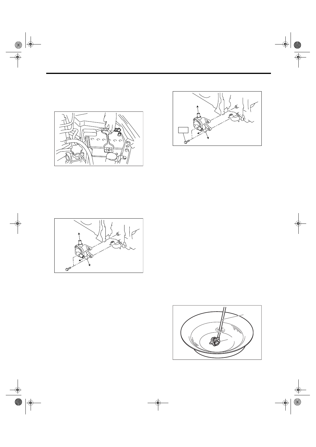
24.ATF Warmer Cock
A: REMOVAL
1) Set the vehicle on a lift.
2) Remove the collector cover.
3) Disconnect the ground cable from battery.
4) Lift-up the vehicle.
5) Remove the under cover.
6) Remove the front exhaust pipe.
<Ref. to EX(H6DO)-4, REMOVAL, Front Exhaust
Pipe.>
7) Disconnect the water hose from ATF warmer
cock.
8) Remove the ATF warmer cock from cylinder
head.
B: INSTALLATION
Install in the reverse order of removal.
Tightening torque:
16 N
⋅
m (1.6 kgf-m, 11.8 ft-lb)
C: INSPECTION
Replace the thermostat if the valve does not close
completely at an ambient temperature or if the fol-
lowing test shows unsatisfactory results.
• Inspection method
Immerse the thermostat and a thermometer in wa-
ter. Raise water temperature gradually, and mea-
sure the temperature and valve lift when the valve
begins to open and when the valve is fully opened.
During the test, agitate the water for even temper-
ature distribution. The measured value should
meet the specification.
NOTE:
• Leave the thermostat in the boiling water for
more than five minutes before measuring the valve
lift.
• Hold the thermostat with a wire or the like to
avoid contacting with the bottom of container.
Starting temperature to open:
69 — 73
°
C (156 — 163
°
F)
Fully opens:
84
°
C (183
°
F)
Valve lift:
8.0 mm (0.315 in) or more
(A) Water pipe
(B) ATF warmer
IN-00203
(B)
(A)
(A)
ME-02074
(A) Water pipe
(B) ATF warmer
(A) Thermometer
(B) Thermostat
(B)
(A)
(A)
ME-02075
T
CO-00033
( A )
( B )
ME(H6DO)-82
MECHANICAL
Intake And Exhaust Valve
25.Intake And Exhaust Valve
A: SPECIFICATION
Refer to “Cylinder Head” for removal and installa-
tion procedures of intake and exhaust valves. <Ref.
to ME(H6DO)-60, REMOVAL, Cylinder Head.>
<Ref. to ME(H6DO)-60, INSTALLATION, Cylinder
Head.>
Нет комментариевНе стесняйтесь поделиться с нами вашим ценным мнением.
Текст