Subaru Legacy IV (2008 year). Service manual — part 750

5AT(diag)-15
Transmission Control Module (TCM) I/O Signal
AUTOMATIC TRANSMISSION (DIAGNOSTICS)
H & LR/C solenoid
output
B54
5
While driving at 2nd of
manual mode
5 V or more
3 — 9
:
(ATF temperature
20°C (68°F))
Drive frequency:
300 Hz
While driving at 1st,
3rd-5th of manual
mode
Less than 1.5 V
Power GND
B54
13
Always
Approx. 0 V
—
Analog GND
B54
18
Always
Approx. 0 V
—
Fr/B solenoid output
B54
4
While driving at other
than 4th of manual
mode
5 V or more
3 — 9
:
(ATF temperature
20°C (68°F))
Drive frequency:
300 Hz
While driving at 4th of
manual mode
Less than 1.5 V
L/U solenoid output
B54
7
When lock-up
3 V or more
3 — 9
:
(ATF temperature
20°C (68°F))
Drive frequency:
300 Hz
When not lock-up
Less than 1 V
D/C solenoid output
B54
1
While driving at 1st or
5th of manual mode
5 V or more
3 — 9
:
(ATF temperature
20°C (68°F))
Drive frequency:
300 Hz
While driving at 2nd-4th
of manual mode
Less than 1.5 V
D/C oil pressure
switch input
B54
22
While driving at 1st or
5th of manual mode
6 V or more
While driving at 2nd-4th
of manual mode
Less than 1.5 V
Subaru Select
Monitor
communication line
B55
8
Ignition switch ON
8 V or more
—
Ignition switch OFF
Less than 1 V
Sensor GND
(analog)
B54
16
Always
Approx. 0 V
—
H&LR/C oil pressure
switch input
B54
14
While driving at 2nd of
manual mode
6 V or more
—
While driving at 3rd-5th
of manual mode
Less than 1.5 V
Fwd/B solenoid
output
B54
19
While driving at 1st or
2nd of manual mode
5 V or more
Drive frequency:
300 Hz
While driving at 3rd-5th
of manual mode
Less than 1.5 V
Fwd/B oil pressure
switch input
B54
21
While driving at 1st or
2nd of manual mode
Less than 1.5 V
While driving at 3rd-5th
of manual mode
6 V or more
Front vehicle speed
sensor input
B54
24
While driving at 2nd
and 20 km/h (12 MPH)
of manual mode
Approx. 500 — 700 rpm
—
Use the Subaru
Select Monitor.
While driving at 4th and
80 km/h (50 MPH) of
manual mode
Approx.
2,000 — 2,500 rpm
Use the Subaru
Select Monitor.
Inhibitor switch 1
input
B54
8
Ignition switch ON,
“P” range
Less than 0.5 V
—
Ignition switch ON,
“N” range
5 V or more
Item
Connector
No.
Terminal
No.
Measuring condition
Measured value
Resistance
between terminal
and chassis
ground
Remarks

5AT(diag)-16
Transmission Control Module (TCM) I/O Signal
AUTOMATIC TRANSMISSION (DIAGNOSTICS)
Inhibitor switch 2
input
B54
9
Ignition switch ON,
“P” range
5 V or more
—
Ignition switch ON,
“D” range
Less than 0.5 V
Lateral G sensor
signal
B55
9
Ignition switch ON
2.0 — 3.0
—
Ignition power
supply
B54
27
Ignition switch ON
8 V or more
—
Ignition switch OFF
Less than 1 V
Rear vehicle speed
sensor input
B54
23
While driving at 2nd
and 20 km/h (12 MPH)
of manual mode
Approx. 500 — 700 rpm
—
Use the Subaru
Select Monitor.
While driving at 4th and
80 km/h (50 MPH) of
manual mode
Approx.
2,000 — 2,500 rpm
Use the Subaru
Select Monitor.
Fr/B oil pressure
switch input
B54
15
While driving at other
than 4th of manual
mode
Less than 1.5 V
—
While driving at 4th of
manual mode
6 V or more
Turbine speed
sensor 1 input
B54
26
2nd of manual mode,
turbine speed sensor is
2,000 rpm (Read from
Subaru Select Monitor)
Approx. 0 rpm
—
Use the Subaru
Select Monitor.
4th of manual mode,
turbine speed sensor is
2,000 rpm (Read from
Subaru Select Monitor)
Approx.
1,900 — 2,100 rpm
Use the Subaru
Select Monitor.
Lateral G sensor
power supply output
B55
7
Ignition switch ON
(when lateral G sensor
is in horizontal position)
4.75 — 5.25
—
Inhibitor switch 3
input
B54
10
Ignition switch ON,
“R” range
5 V or more
—
Ignition switch ON,
“D” range
Less than 0.5 V
Control GND1
B55
23
Ignition switch ON
Approx. 0 V
Ignition switch OFF
Control GND2
B55
22
Ignition switch ON
Approx. 0 V
Ignition switch OFF
Inhibitor switch 4
input
B54
11
Ignition switch ON,
“P” range
Less than 0.5 V
—
Ignition switch ON,
“D” range
5 V or more
Back-up light relay
output
B55
13
Ignition switch ON,
“R” range
Less than 1 V
90 — 110
:
(ATF temperature
25°C (77°F))
Ignition switch ON,
other than “R” range
8 V or more
AWD solenoid
output
B54
2
Engine ON, “P” range
or “N” range,
accelerator OFF
Less than 1 V
3 — 9
:
(ATF temperature
20°C (68°F))
Drive frequency:
300 Hz
Engine ON, “D” range,
accelerator OFF,
brake ON
2 V or more
Item
Connector
No.
Terminal
No.
Measuring condition
Measured value
Resistance
between terminal
and chassis
ground
Remarks

5AT(diag)-17
Transmission Control Module (TCM) I/O Signal
AUTOMATIC TRANSMISSION (DIAGNOSTICS)
Turbine speed
sensor 2 input
B54
25
2nd of manual mode,
turbine speed sensor is
2,000 rpm (Read from
Subaru Select Monitor)
Approx.
1,200 — 1,500 rpm
—
Use the Subaru
Select Monitor.
4th of manual mode,
turbine speed sensor is
2,000 rpm (Read from
Subaru Select Monitor)
Approx.
1,900 — 2,100 rpm
—
Use the Subaru
Select Monitor.
PN signal output
B55
11
Ignition switch ON,
Other than “P” range or
“N” range
8 V or more
—
Ignition switch ON,
“P” range or “N” range
Less than 1 V
—
Ignition power
supply 1
B55
26
Ignition switch ON
8 V or more
Ignition switch OFF
Ignition power
supply 2
B55
19
Ignition switch ON
8 V or more
Ignition switch OFF
Less than 1 V
Ignition power
supply 3
B55
18
Ignition switch ON
8 V or more
Ignition switch OFF
Less than 1 V
Ignition power
supply 4
B55
25
Ignition switch ON
8 V or more
Ignition switch OFF
Item
Connector
No.
Terminal
No.
Measuring condition
Measured value
Resistance
between terminal
and chassis
ground
Remarks
5AT(diag)-18
Subaru Select Monitor
AUTOMATIC TRANSMISSION (DIAGNOSTICS)
6. Subaru Select Monitor
A: OPERATION
1. READ DIAGNOSTIC TROUBLE CODE
(DTC)
1) Prepare the Subaru Select Monitor kit. <Ref. to
5AT(diag)-7, PREPARATION TOOL, General De-
scription.>
2) Prepare PC with Subaru Select Monitor in-
stalled.
3) Connect the USB cable between SDI (Subaru
Diagnosis Interface) and USB port on the personal
computer (dedicated port for the Subaru Select
Monitor).
NOTE:
The dedicated port for the Subaru Select Monitor
means the USB port which was used to install the
Subaru Select Monitor.
4) Connect the diagnosis cable to SDI.
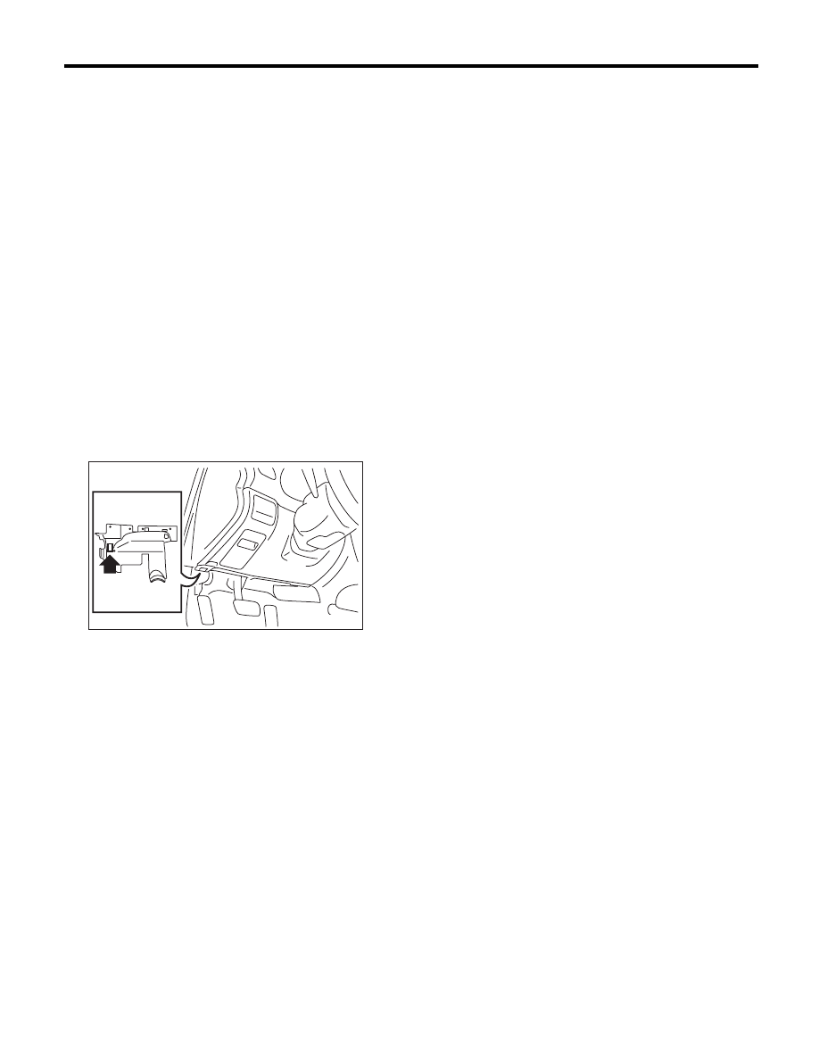
5) Connect SDI to data link connector located in the
lower portion of the instrument panel (on the driv-
er’s side).
CAUTION:
Do not connect scan tools other than the Suba-
ru Select Monitor.
6) Start the PC.
7) Turn the ignition switch to ON (engine OFF) and
run the “PC application for Subaru Select Monitor”.
8) On the «Main Menu» display, select the {Each
System Check}.
9) On the «System Selection Menu» display, select
the {Transmission Control System}.
10) After transmission type information pops up,
select [OK].
11) On the «Transmission Diagnosis» display, se-
lect the {Diagnostic Code(s) Display}.
12) On the «Diagnostic Code(s) Display» display,
select the {Temporary Diagnostic Code(s)} or
{Memorized Diagnostic Code(s)}
2. READ CURRENT DATA
1) On the «Main Menu» display, select the {Each
System Check}.
2) On the «System Selection Menu» display, select
the {Transmission Control System}.
3) After transmission type information pops up, se-
lect [OK].
4) On the «Transmission Diagnosis» display, se-
lect the {Current Data Display & Save}.
5) On the «Current Data Display & Save» display,
select the {Normal sampling}.
AT-04371
Нет комментариевНе стесняйтесь поделиться с нами вашим ценным мнением.
Текст