Subaru Legacy IV (2008 year). Service manual — part 971
PS-46
Oil Pump
POWER ASSISTED SYSTEM (POWER STEERING)
B: INSTALLATION
1. H4 MODEL
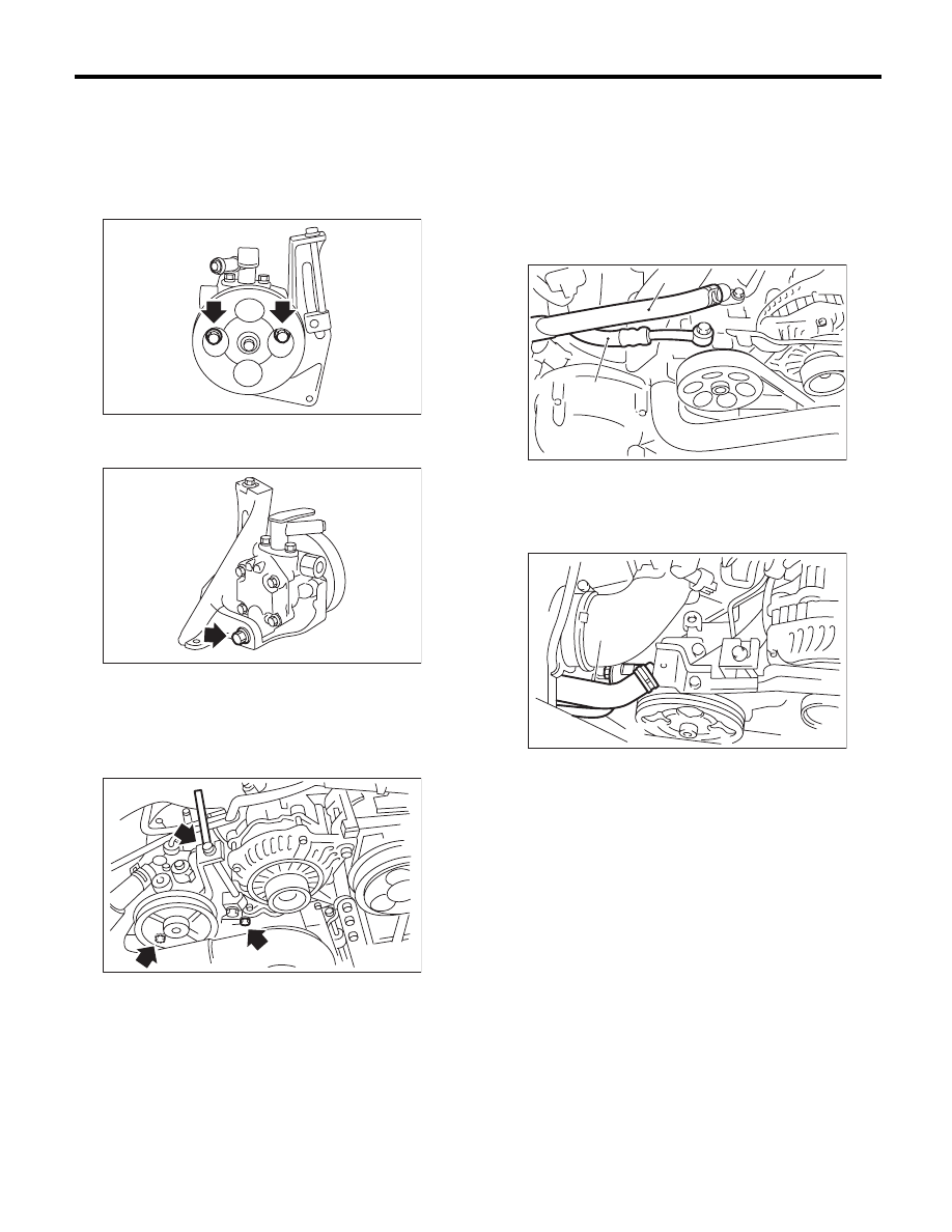
1) Install the oil pump to the bracket.
Tightening torque:
15.7 N·m (1.6 kgf-m, 11.6 ft-lb)
Tightening torque:
48.4 N·m (4.9 kgf-m, 35.7 ft-lb)
2) Attach the installation bolts of the power steering
pump bracket.
Tightening torque:
<Ref. to PS-6, OIL PUMP, COMPONENT, Gen-
eral Description.>
3) After installing the oil pump, fill the fluid while ro-
tating the pulley by hand to bleed air from the oil
pump.
CAUTION:
Always fill the oil pump with the fluid to prevent
abnormal noise and seizure of the oil pump.
4) Connect the pressure hose and suction hose.
Tightening torque:
Eye bolt
40 N·m (4.1 kgf-m, 29.5 ft-lb)
CAUTION:
Be careful not to twist hoses. Twisted hoses
may contact other parts.
• Non-turbo model
• Turbo model
5) Connect the power steering pressure switch
connector.
6) Install the V-belts to the oil pump.
7) Check the tension of the V-belt.
<Ref. to ME(H4SO)-40, INSPECTION, V-belt.>
8) Tighten the lock bolt of the belt tension nut.
Tightening torque:
25 N·m (2.5 kgf-m, 18.4 ft-lb)
9) Install the pulley belt cover.
10) Install the air intake duct.
<Ref. to IN(H4DOTC)-9, INSTALLATION, Air In-
take Duct.> <Ref. to IN(H4SO)-8, INSTALLATION,
Air Intake Duct.>
11) Connect the ground cable to battery.
PS-00128
PS-00137
PS-00188
(1) Suction hose
(2) Pressure hose
(1) Suction hose
(2) Pressure hose
PS-00688
(1)
(2)
(2)
PS-00459
(1)
PS-47
Oil Pump
POWER ASSISTED SYSTEM (POWER STEERING)
12) Fill with the specified power steering fluid.
<Ref. to PS-53, Power Steering Fluid.>
CAUTION:
Never start the engine before filling with fluid;
otherwise the vane pump may become seized.
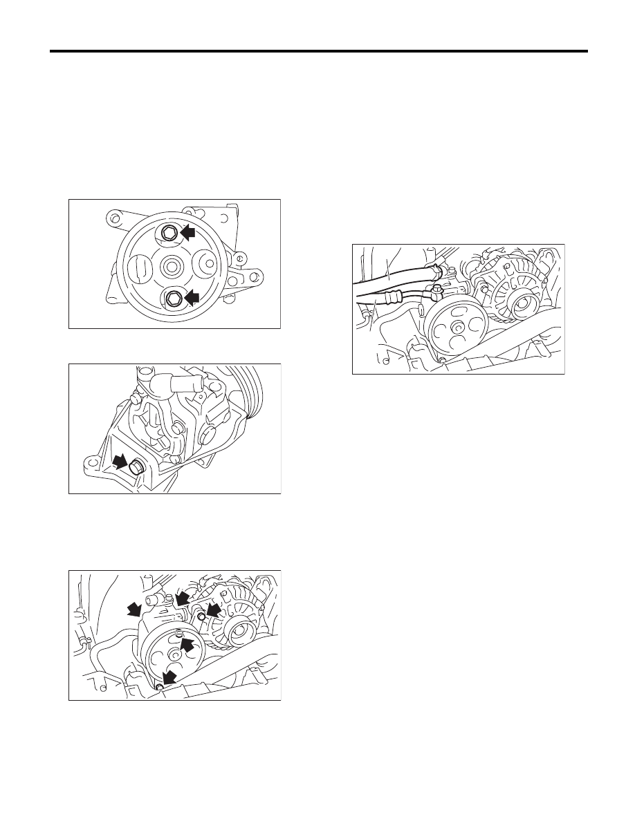
2. H6 MODEL
1) Install the oil pump to the bracket.
Tightening torque:
15.7 N·m (1.6 kgf-m, 11.6 ft-lb)
Tightening torque:
37.3 N·m (3.8 kgf-m, 27.5 ft-lb)
2) Tighten the bolt which attaches the power steer-
ing pump bracket.
Tightening torque:
<Ref. to PS-6, OIL PUMP, COMPONENT, Gen-
eral Description.>
3) After installing the oil pump, fill the fluid while ro-
tating the pulley by hand to bleed air from the oil
pump.
CAUTION:
Always fill the oil pump with the fluid to prevent
abnormal noise and seizure of the oil pump.
4) Connect the pressure hose and suction hose.
Tightening torque:
Eye bolt
40 N·m (4.1 kgf-m, 29.5 ft-lb)
CAUTION:
Be careful not to twist hoses. Twisted hoses
may contact other parts.
5) Connect the power steering pressure switch
connector.
6) Install the tensioner adjuster.
7) Install the V-belts.
8) Install the pulley belt cover.
9) Connect the ground cable to battery.
10) Pour the specified power steering fluid. <Ref. to
PS-53, Power Steering Fluid.>
CAUTION:
Never start the engine before filling with fluid;
otherwise the vane pump may become seized.
PS-00229
PS-00702
PS-00701
(1) Suction hose
(2) Pressure hose
PS-00700
(1)
(2)

PS-48
Oil Pump
POWER ASSISTED SYSTEM (POWER STEERING)
C: INSPECTION
1. BASIC INSPECTION
Perform the following inspection procedures and replace faulty parts.
No.
Parts
Inspection
Corrective action
1
Oil pump (Exterior)
(1) Crack, damage or oil leakage
Replace the oil pump with a new part.
(2) Play of pulley shaft
Measure the radial play and axial play.
If any of these exceeds the service limit, replace the
oil pump with a new part.
2
Pulley
(1) Damage
Replace with a new part.
(2) Bend
Measure the V groove deflection.
If it exceeds the service limit, replace the pulley with a
new part.
3
Oil pump (Interior)
(1) Faulty or seized of vane pump
Check the rotating resistance of pulley.
If it exceeds the service limit, replace the oil pump with
new part.
(2) Bend in the shaft or damage to
bearing
If the a string is wrapped on the pulley and rotated,
and the oil pump emits a noise that is markedly differ-
ent in tone and loudness from a sound of a new oil
pump, replace the oil pump with a new part.
4
O-ring
Cracking or deterioration
Replace with a new part.
5
Bracket
Crack
Replace with a new part.
PS-49
Oil Pump
POWER ASSISTED SYSTEM (POWER STEERING)
2. SERVICE LIMIT
Make a measurements as follows. If it exceeds the
service limit, replace with a new part.
CAUTION:
• When securing the oil pump on a vise, hold
the oil pump with the least possible force be-
tween two pieces of wood.
• Do not set the outside of flow control valve or
pulley on a vise; otherwise outside or pulley
might be deformed. Select properly sized wood
pieces.
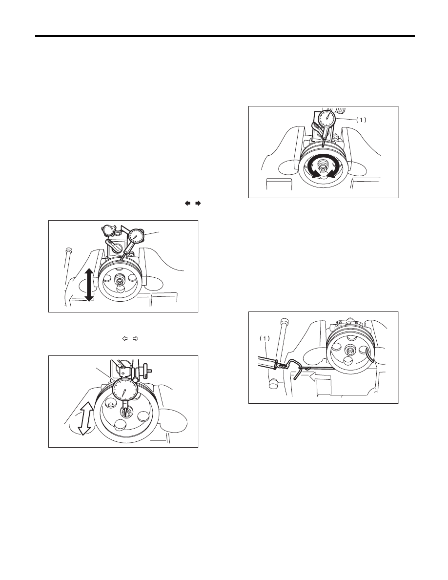
1) Play of the pulley shaft
Condition:
P: When applying the force of 9.8 N
(1.0 kgf, 2.2 lb)
Service limit:
Play in the radial direction (Direction
)
0.4 mm (0.016 in) or less
Axial play (Direction
)
0.9 mm (0.035 in) or less
2) Deflection of the pulley groove
Service limit:
1.0 mm (0.039 in) or less
NOTE:
Read the value for one surface of V ditch, and then
the value for another off the dial gauge.
3) Rotating resistance of pulley
Service limit:
Maximum load: 9.22 N (0.94 kgf, 2.07 lb) or
less
NOTE:
• A rather higher value may be indicated when pul-
ley starts turning.
• Measure the load during rotation to make a judg-
ment.
(1) Dial gauge
(1) Dial gauge
PS-00145
P
(1)
PS-00146
P
(1)
(1) Dial gauge
(1) Spring scale
PS-00147
PS-00148
Нет комментариевНе стесняйтесь поделиться с нами вашим ценным мнением.
Текст