Subaru Legacy IV (2008 year). Service manual — part 380

EN(H4DOTC)(diag)-341
Diagnostic Procedure with Diagnostic Trouble Code (DTC)
ENGINE (DIAGNOSTICS)
Step
Check
Yes
No
1
CHECK OUTPUT SIGNAL OF ECM.
1) Turn the ignition switch to ON.
2) Measure the voltage between ECM and
chassis ground.
Connector & terminal
(B136) No. 7 (+) — Chassis ground (–):
Is the voltage 10 V or more?
Repair the poor
contact of ECM
connector.
Go to step 2.
2
CHECK HARNESS BETWEEN ECM AND
PURGE CONTROL SOLENOID VALVE 2.
1) Turn the ignition switch to OFF.
2) Disconnect the connectors from ECM and
purge control solenoid valve 2.
3) Measure the resistance between the purge
control solenoid valve 2 connector and engine
ground.
Connector & terminal
(E52) No. 2 — Engine ground:
Is the resistance 1 M
: or
more?
Go to step 3.
Repair the ground
short circuit of har-
ness between
ECM and purge
control solenoid
valve 2 connector.
3
CHECK HARNESS BETWEEN ECM AND
PURGE CONTROL SOLENOID VALVE 2.
Measure the resistance of harness between
ECM and purge control solenoid valve 2.
Connector & terminal
(B136) No. 7 — (E52) No. 2:
Is the resistance less than 1
:? Go to step 4.
Repair the harness
and connector.
NOTE:
In this case, repair
the following item:
• Open circuit of
harness between
ECM and purge
control solenoid
valve 2 connector
• Poor contact of
coupling connector
4
CHECK PURGE CONTROL SOLENOID
VALVE 2.
1) Remove the purge control solenoid valve 2.
2) Measure the resistance between purge con-
trol solenoid valve 2 terminals.
Terminals
No. 1 — No. 2:
Is the resistance between 10 —
100
:?
Go to step 5.
Replace the purge
control solenoid
valve 2. <Ref. to
EC(H4DOTC)-9,
Purge Control
Solenoid Valve.>
5
CHECK POWER SUPPLY TO PURGE CON-
TROL SOLENOID VALVE 2.
1) Turn the ignition switch to ON.
2) Measure the voltage between purge control
solenoid valve 2 and engine ground.
Connector & terminal
(E52) No. 1 (+) — Engine ground (–):
Is the voltage 10 V or more?
Repair the poor
contact in the
purge control sole-
noid valve 2 con-
nector.
Repair the harness
and connector.
NOTE:
In this case, repair
the following item:
• Open circuit of
harness between
the main relay and
purge control sole-
noid valve 2
• Poor contact of
coupling connector
• Poor contact of
main relay connec-
tor
EN(H4DOTC)(diag)-342
Diagnostic Procedure with Diagnostic Trouble Code (DTC)
ENGINE (DIAGNOSTICS)
EB:DTC P2420 EVAPORATIVE EMISSION SYSTEM SWITCHING VALVE CONTROL
CIRCUIT HIGH
DTC DETECTING CONDITION:
• Two consecutive driving cycles with fault
• GENERAL DESCRIPTION <Ref. to GD(H4DOTC)-227, DTC P2420 EVAPORATIVE EMISSION SYS-
TEM SWITCHING VALVE CONTROL CIRCUIT HIGH, Diagnostic Trouble Code (DTC) Detecting Criteria.>
TROUBLE SYMPTOM:
Improper idling
CAUTION:
After repair or replacement of faulty parts, perform Clear Memory Mode <Ref. to EN(H4DOTC)(diag)-
52, OPERATION, Clear Memory Mode.>, and Inspection Mode <Ref. to EN(H4DOTC)(diag)-43, PRO-
CEDURE, Inspection Mode.>.
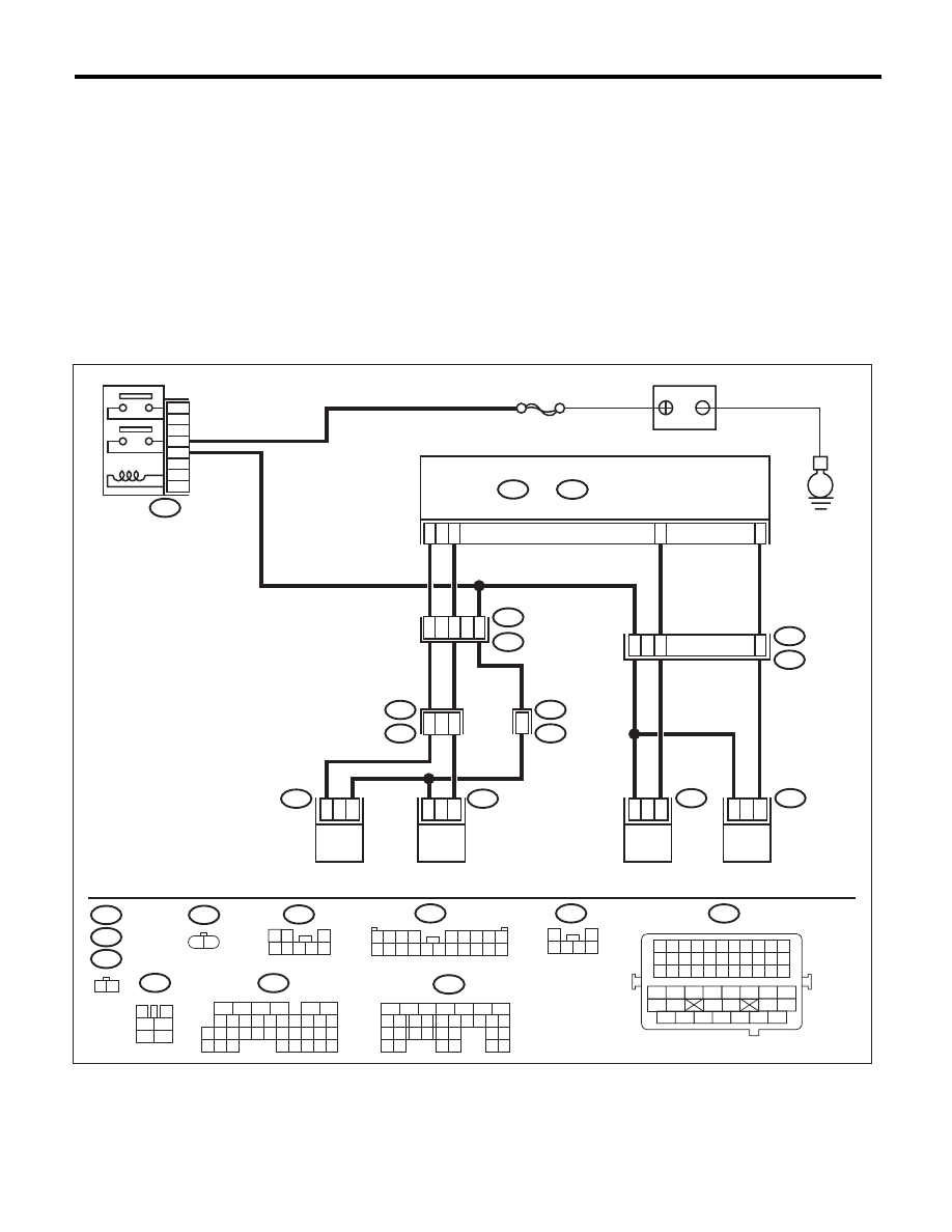
WIRING DIAGRAM:
EN-05679
SBF-7
E4
B47
E
5
3
6
4
2
1
2
1
C17
C28
D29
C7
R15
R213
R68
R144
R1
B97
14
15
2
2
1
1
7
1
5
E52
2
1
E52
R144
E4
B47
R67
B97
R213
R68
1 2
3
4
1
2
5
6
B21
1 2
1 2
3
4 5 6 7 8
1 2 3 4 5 6 7 8 9 10 11
12 13 14 15 16 17 18 19 20 21 22
23 24 25 26 27 28 29 30 31 32 33
34
35
42
43
36
37
38
39
48
49
50
51
52
53
54
40
41
44
45
46
47
1
2
3 4 5 6
1 2 3 4
5 6 7 8 9
10 11 12 13 14 15 16 17 18 19 20
R46
R67
6
B21
E2
11
48
16
10 11 12 13 14 15
25
24
30
9
8
7
17 18 19 20
28
21 22 23
29
32
31
1
2
3
4
5
6
27
26
33 34 35
B136
C:
B137
5
6
7
8
2
1
9
4
3
10
22 23
11 12 13 14 15
24 25
26
16 17
18 19 20 21
27
28 29
30 31
D:
B136
C:
B137
D:
44
MAIN RELAY
ECM
BATTERY
DRAIN VALVE
PRESSURE
CONTROL
SOLENOID VALVE
PURGE CONTROL
SOLENOID VALVE 1
PURGE CONTROL
SOLENOID VALVE 2

EN(H4DOTC)(diag)-343
Diagnostic Procedure with Diagnostic Trouble Code (DTC)
ENGINE (DIAGNOSTICS)
Step
Check
Yes
No
1
CHECK HARNESS BETWEEN ECM AND
PURGE CONTROL SOLENOID VALVE 2.
1) Turn the ignition switch to OFF.
2) Disconnect the connectors from ECM and
purge control solenoid valve 2.
3) Turn the ignition switch to ON.
4) Measure the voltage between ECM and
chassis ground.
Connector & terminal
(B136) No. 7 (+) — Chassis ground (–):
Is the voltage 10 V or more?
Repair the short to
power in the har-
ness between
ECM and purge
control solenoid
valve 2 connector.
Go to step 2.
2
CHECK PURGE CONTROL SOLENOID
VALVE 2.
1) Turn the ignition switch to OFF.
2) Measure the resistance between purge con-
trol solenoid valve 2 terminals.
Terminals
No. 1 — No. 2:
Is the resistance less than 1
:? Replace the purge
control solenoid
valve 2. <Ref. to
EC(H4DOTC)-9,
Purge Control
Solenoid Valve.>
Repair the poor
contact of ECM
connector.
EN(H4DOTC)(diag)-344
Diagnostic Procedure with Diagnostic Trouble Code (DTC)
ENGINE (DIAGNOSTICS)
EC:DTC P2431 SECONDARY AIR INJECTION SYSTEM AIR FLOW /PRESSURE
SENSOR CIRCUIT RANGE/PERFORMANCE
DTC DETECTING CONDITION:
• Two consecutive driving cycles with fault
• GENERAL DESCRIPTION <Ref. to GD(H4DOTC)-228, DTC P2431 SECONDARY AIR INJECTION SYS-
TEM AIR FLOW /PRESSURE SENSOR CIRCUIT RANGE/PERFORMANCE, Diagnostic Trouble Code
(DTC) Detecting Criteria.>
CAUTION:
After repair or replacement of faulty parts, perform Clear Memory Mode <Ref. to EN(H4DOTC)(diag)-
52, OPERATION, Clear Memory Mode.>, and Inspection Mode <Ref. to EN(H4DOTC)(diag)-43, PRO-
CEDURE, Inspection Mode.>.
Нет комментариевНе стесняйтесь поделиться с нами вашим ценным мнением.
Текст