Subaru Legacy IV (2008 year). Service manual — part 1190
WI-12
Basic Diagnostic Procedure
WIRING SYSTEM
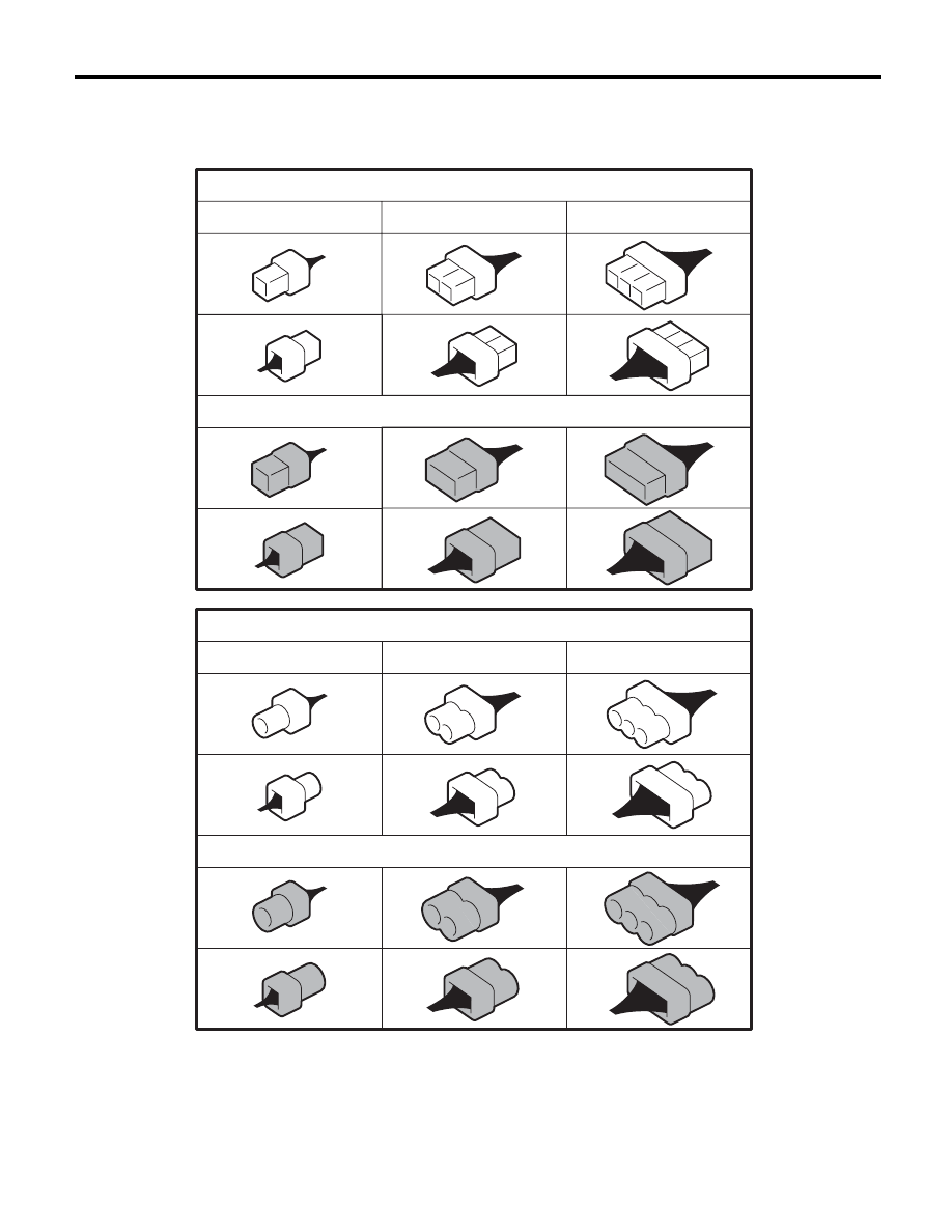
E: CONNECTOR SYMBOL IN WIRING HARNESS
A number of connector symbols are used in each wiring diagram to easily identify the wiring harness con-
nectors.
WI-02756
Standard type: Female
Standard type: Male
Water proof type: Female
Water proof type: Male
Pole: From 1 to 8
Pole: From 9 to 20
Pole: More than 21
Pole: From 1 to 8
Pole: From 9 to 20
Pole: More than 21

WI-13
Basic Diagnostic Procedure
WIRING SYSTEM
F: ABBREVIATION IN WIRING DIAGRAMS
Abbr.
Full name
A/B
Airbag
A/C
Air Conditioner
A/F
Air/Fuel (Air fuel ratio sensor)
ABS
Anti-lock Brake System
ACC
Accessory
ALT
Generator
ASSY
Assembly
AT
Automatic Transmission
ATF
Automatic transmission fluid
AWD
All Wheel Drive
B, BAT
Battery
CAN
Communication Area Network
CPU
Central Processing Unit
D
Drive Range
D, DN
Down
E
Ground
ECO
Economy
ECM
Engine Control Module (ECM)
EGR
Exhaust Gas Recirculation
F/B
Fuse & Relay box
FL
Front Left
FR
Front Right
FWD
Front Wheel Drive
G
Gravity (G sensor)
H/L
Headlight
HI
High
HID
High Intensity Discharge
I/F
Interface
IG
Ignition
Illumi.
Illumination
INT
Intermittent
LCD
Liquid Crystal Display
LH
Left Hand
Lo
Low
M
Motor
M/B
Main Fuse Box
MG
Magnet
Mi
Middle
MT
Manual Transmission
MID
Multi Information Display
MIST
Wiper mist (One-touch)
MT
Manual Transmission
N
Neutral Range
NA
Natural Aspiration
NAVI
Navigation
OP
Optional Parts or Open
P
Parking Range
PASS
Passing
PCV
Positive Crankcase Ventilation Valve
R
Reverse Range
R, RH
Right Hand
RL
Rear Left
RR
Rear Right
SBF
Slow Blow Fuse
SI-DRIVE
SUBARU Intelligent Drive
S/S
SPORT Shift
ST
Starter
SW
Switch
TB
Turbo
TCM
Transmission Control Module
TPM
Tire Pressure Monitor
TPMS
Tire Pressure Monitor System
TV
Television
U, UP
Up
VDC
Vehicle Dynamics Control
VICS
Vehicle Information and Communication
System
WASH
Washer
Abbr.
Full name
WI-14
Working Precautions
WIRING SYSTEM
2. Working Precautions
A: PRECAUTIONS WHEN WORKING
WITH THE PARTS MOUNTED ON
THE VEHICLE
1) When working under a vehicle which is jacked-
up, always be sure to use rigid rack.
2) The parking brake must always be applied dur-
ing working. Also, in automatic transmission vehi-
cles, keep the select lever set to the P (Parking)
range.
3) Be sure the workshop is properly ventilated
when running the engine. Further, be careful not to
touch the belt or fan while the engine is operating.
4) Be careful not to touch hot metal parts, especial-
ly the radiator and exhaust system immediately af-
ter the engine has been turned off.
B: PRECAUTIONS IN TROUBLE
DIAGNOSIS AND REPAIR OF
ELECTRIC PARTS
1) The battery cable must be disconnected from
the battery’s (–) terminal, and the ignition switch
must be set to the OFF position, unless otherwise
required by the diagnostics.
2) Securely fasten the wiring harness with clamps
and clips so that the harness does not interfere with
the body end parts or edges and bolts or screws.
3) When installing parts, be careful not to catch
them on the wiring harness.
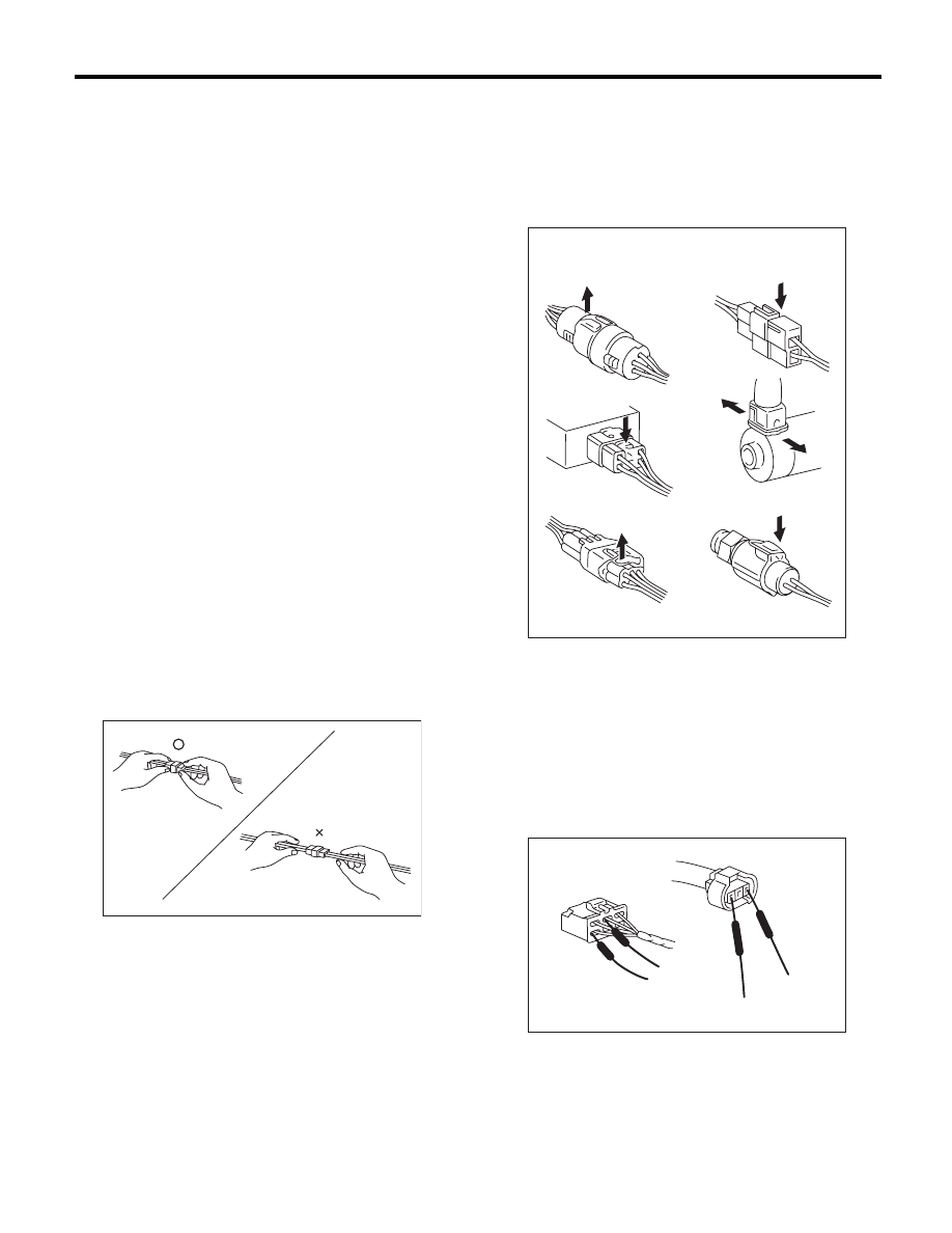
4) When disconnecting a connector, do not pull the
wires, but pull while holding the connector body.
5) Some connectors are provided with a lock. One
type of such a connector is disconnected by push-
ing the lock, and the other, by moving the lock up.
In either type the lock shape must be identified be-
fore attempting to disconnect the connector.
To connect, insert the connector until it snaps and
confirm that it is connected securely.
6) When checking continuity between connector
terminals, or measuring voltage across the terminal
and ground, always contact tester probe(s) on ter-
minals from the wiring connection side. If the probe
is too thick to gain access to the terminal, use “mini”
test leads.
To check water-proof connectors (which are not
measurable from the wiring side), contact test
probes on the terminal side. Be careful not to bend
or damage the terminals.
7) Sensors, relays, electrical unit, etc., are sensi-
tive to strong impacts.
Handle them with care so that they are not dropped
or mishandled.
WI-02757
WI-02758
EXAMPLE
WI-09366
WI-15
Power Supply Circuit
WIRING SYSTEM
3. Power Supply Circuit
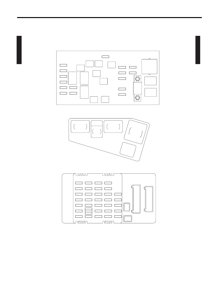
A: WIRING DIAGRAM
WI-13119
P-SUP-01
P-SUP-01
MAIN FUSE BOX (M/B)
FUSE & RELAY BOX (F/B)
H/L
RELAY
RH
MAIN
FAN
RELAY-1
MAIN
SBF
H/L
RELAY
LH
NO. 8
NO. 11
NO. 12
NO. 13
NO. 14
NO. 15
NO. 16
NO. 27
NO. 28
NO. 29
NO. 30
NO. 31
NO. 32
NO. 33
NO. 20
NO. 21
NO. 22
NO. 23
NO. 24
NO. 25
NO. 26
NO. 13
NO. 14
NO. 15
NO. 16
NO. 17
NO. 18
NO. 19
NO. 6
NO. 7
NO. 8
NO. 9
NO. 10
NO. 11
NO. 12
NO. 1
NO. 2
NO. 3
NO. 4
NO. 5
NO. 9
NO. 10
NO. 3
NO. 4
NO. 1
NO. 2
NO. 5
NO. 6
NO. 7
SBF-8
SBF-6
SBF-2
SBF-3
SBF-4
SBF-7
SBF-5
SBF-1
HORN
RELAY
R.DEF
RELAY
TAIL
RELAY
SECONDARY AIR FUSE & RELAY BOX
SBF-9
AIR CUT
RELAY 1
AIR
CUT
No. 17
AIR CUT
RELAY 2
AIR
PUMP
RELA
Y
Нет комментариевНе стесняйтесь поделиться с нами вашим ценным мнением.
Текст