Subaru Legacy IV (2008 year). Service manual — part 390
GD(H4DOTC)-10
Diagnostic Trouble Code (DTC) Detecting Criteria
GENERAL DESCRIPTION
2. Diagnostic Trouble Code (DTC) Detecting Criteria
A: DTC P0011 INTAKE CAMSHAFT POSITION - TIMING OVER-ADVANCED OR
SYSTEM PERFORMANCE (BANK 1)
1. OUTLINE OF DIAGNOSIS
Detect the AVCS system malfunction.
Judge NG when the amount of AVCS actual timing advance does not approach to the amount of AVCS target
timing advance.
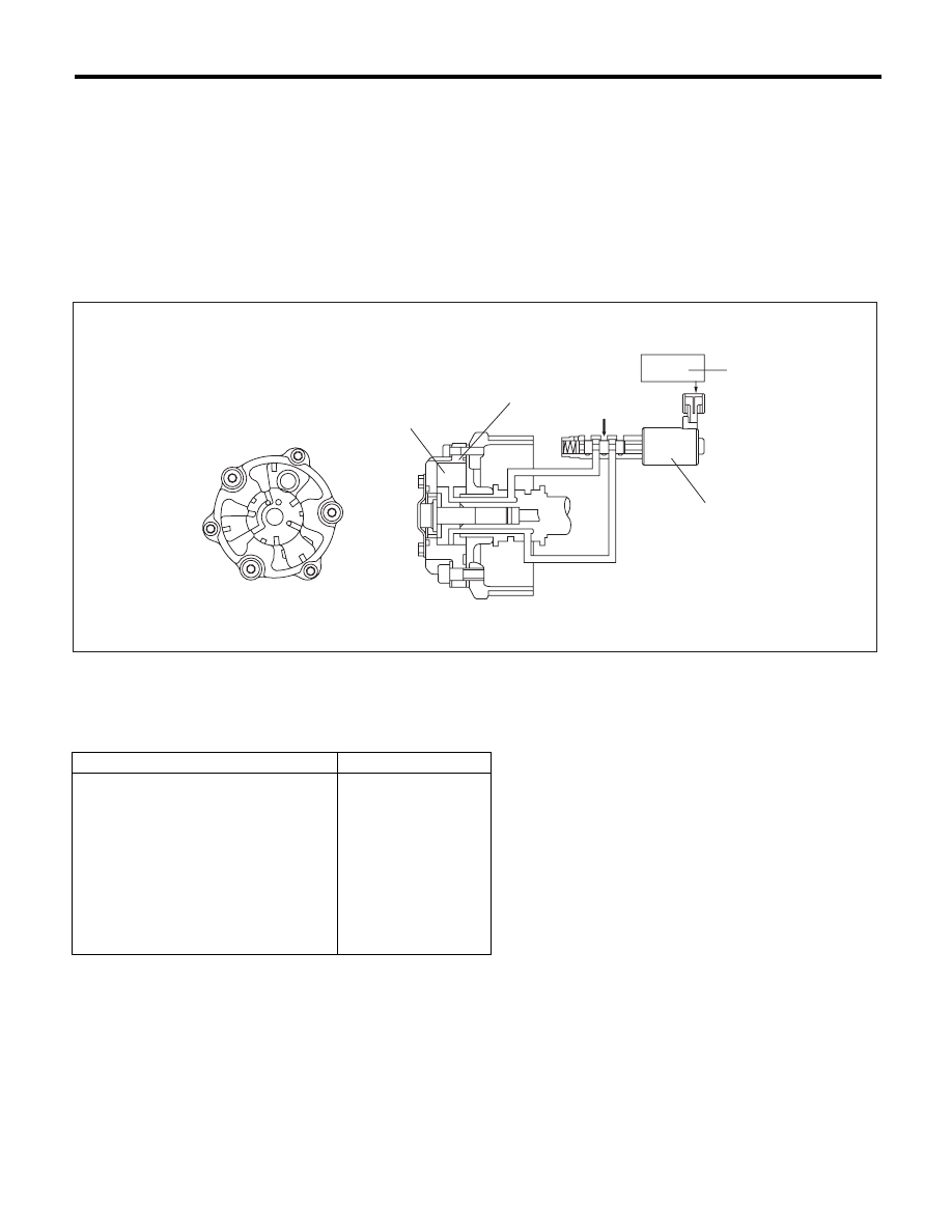
2. COMPONENT DESCRIPTION
3. ENABLE CONDITION
4. GENERAL DRIVING CYCLE
Perform the diagnosis continuously after warming up when the engine speed increases and AVCS operates.
(1)
AVCS timing controller
(3)
Engine control module (ECM)
(5)
Oil pressure
(2)
Vane
(4)
Oil flow control solenoid valve
Secondary Parameters
Enable Conditions
Time of establishing all secondary
parameter conditions
t 3000 ms
Battery voltage
t 10.9 V
Engine speed
t 1300 rpm
Engine coolant temperature
t 60 °C (140 °F)
AVCS control
Operation
Target advance angle
t 0 °CA
Target timing advance change amount
(per 64 ms)
< 1.07 °CA
EN-01852
(3)
(4)
(1)
(5)
(2)

GD(H4DOTC)-11
Diagnostic Trouble Code (DTC) Detecting Criteria
GENERAL DESCRIPTION
5. DIAGNOSTIC METHOD
1) When the conditions during which the differences of AVCS target timing advance amount and AVCS ac-
tual timing advance amount is large continues for certain amount of time.
2) When the differences of target timing advance amount and actual timing advance amount is calculated
during AVCS control, and the difference per predetermined time is the specified value or larger.
• Abnormality Judgement
Judge as NG when the following conditions are established within the predetermined time.
Time Needed for Diagnosis:
• AT model: 30000 ms
• MT model: 20000 ms
Malfunction Indicator Light Illumination: Illuminates when malfunction occurs in 2 continuous driving cycles.
• Normality Judgement
Judge as OK and clear the NG if the following conditions are established within the predetermined time.
Time Needed for Diagnosis:
• AT model: 30000 ms
• MT model: 20000 ms
Judgement Value
Malfunction Criteria
Threshold Value
6(Target position – Actual position)
> 8000 °CA (AT model)
(Bank 1)
> 8000 °CA (AT model)
(Bank 2)
> 5300 °CA (MT model)
(Bank 1)
> 5300 °CA (MT model)
(Bank 2)
or
6(Target position – Actual position)
< –8000 °CA (AT model)
(Bank 1)
< –8000 °CA (AT model)
(Bank 2)
< –5300 °CA (MT model)
(Bank 1)
< –5300 °CA (MT model)
(Bank 2)
Judgement Value
Malfunction Criteria
Threshold Value
6(Target position – Actual position)
d 8000 °CA (AT model)
(Bank 1)
d 8000 °CA (AT model)
(Bank 2)
d 5300 °CA (MT model)
(Bank 1)
d 5300 °CA (MT model)
(Bank 2)
and
t –8000 °CA (AT model)
(Bank 1)
t –8000 °CA (AT model)
(Bank 2)
t –5300 °CA (MT model)
(Bank 1)
t –5300 °CA (MT model)
(Bank 2)
GD(H4DOTC)-12
Diagnostic Trouble Code (DTC) Detecting Criteria
GENERAL DESCRIPTION
B: DTC P0016 CRANKSHAFT POSITION - CAMSHAFT POSITION CORRELATION
(BANK1)
1. OUTLINE OF DIAGNOSIS
Detect the AVCS system malfunction.
Judge as NG when the timing advance is outside the normal range.
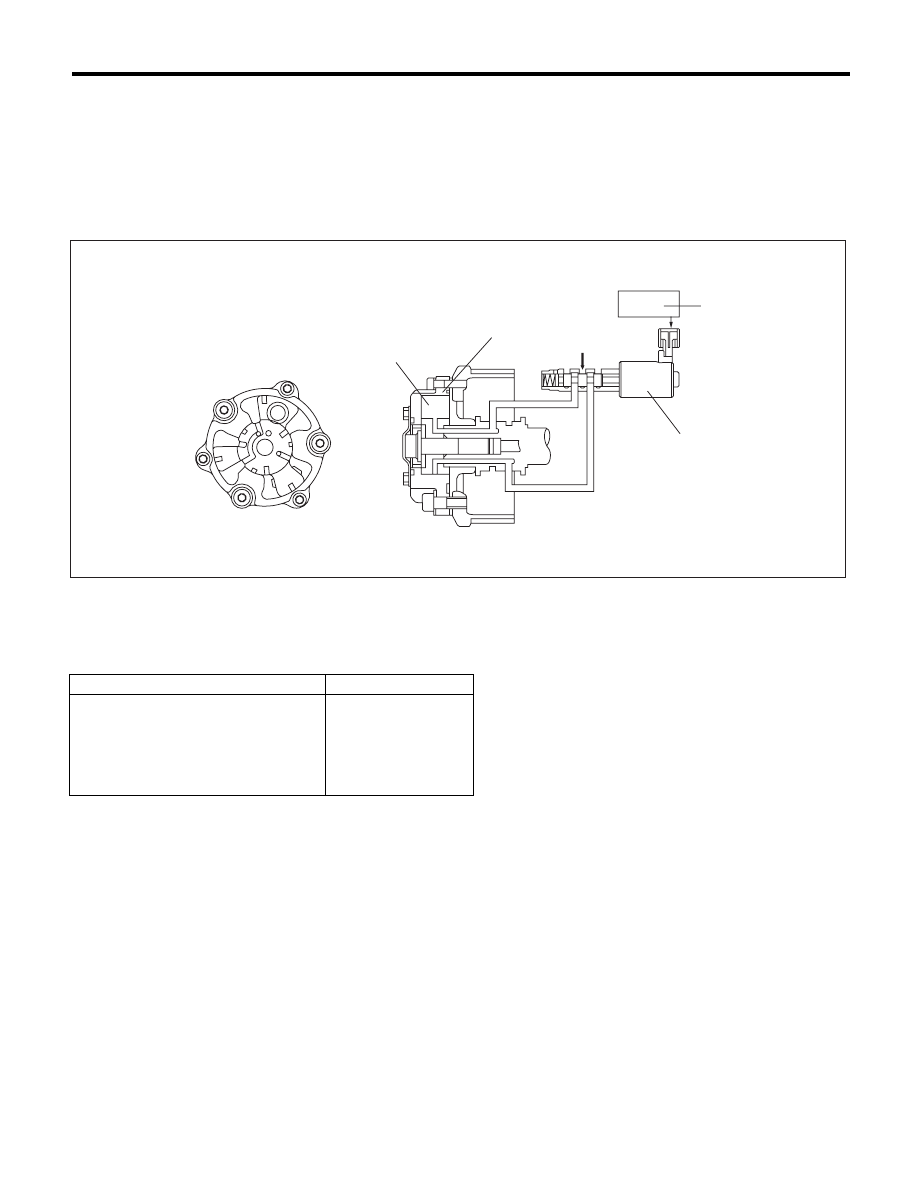
2. COMPONENT DESCRIPTION
3. ENABLE CONDITION
4. GENERAL DRIVING CYCLE
Perform the diagnosis continuously after starting engine and while AVCS is not operating.
(1)
AVCS timing controller
(3)
Engine control module (ECM)
(5)
Oil pressure
(2)
Vane
(4)
Oil flow control solenoid valve
Secondary Parameters
Enable Conditions
Battery voltage
t 10.9 V
Engine speed
t 500 rpm
Engine coolant temperature
t 60 °C (140 °F)
AVCS control
Not in operation
Target timing advance
0°CA
EN-01852
(3)
(4)
(1)
(5)
(2)

GD(H4DOTC)-13
Diagnostic Trouble Code (DTC) Detecting Criteria
GENERAL DESCRIPTION
5. DIAGNOSTIC METHOD
Judge as NG when the camshaft sensor input position is not within the normal range.
• Abnormality Judgement
If the duration of time while the following conditions are met is longer than the time indicated, judge as NG.
Time Needed for Diagnosis: 20000 ms
Malfunction Indicator Light Illumination: Illuminates when malfunction occurs in 2 continuous driving cy-
cles.
• Normality Judgement
Judge as OK and clear the NG if the continuous time while the following conditions are established is more
than the predetermined time.
Time Needed for Diagnosis: 1000 ms
C: DTC P0018 CRANKSHAFT POSITION - CAMSHAFT POSITION CORRELATION
(BANK2)
1. OUTLINE OF DIAGNOSIS
NOTE:
For the detection standard, refer to DTC P0016. <Ref. to GD(H4DOTC)-12, DTC P0016 CRANKSHAFT PO-
SITION - CAMSHAFT POSITION CORRELATION (BANK1), Diagnostic Trouble Code (DTC) Detecting Cri-
teria.>
D: DTC P0021 INTAKE CAMSHAFT POSITION - TIMING OVER-ADVANCED OR
SYSTEM PERFORMANCE (BANK 2)
1. OUTLINE OF DIAGNOSIS
NOTE:
For the detection standard, refer to DTC P0011. <Ref. to GD(H4DOTC)-10, DTC P0011 INTAKE CAM-
SHAFT POSITION - TIMING OVER-ADVANCED OR SYSTEM PERFORMANCE (BANK 1), Diagnostic
Trouble Code (DTC) Detecting Criteria.>
Judgement Value
Malfunction Criteria
Threshold Value
Crankshaft position when camshaft
position sensor signal is input
< BTDC 17 °CA (Bank 1)
< BTDC 17 °CA (Bank 2)
or
> BTDC 55 °CA (Bank 1)
> BTDC 55 °CA (Bank 2)
Judgement Value
Malfunction Criteria
Threshold Value
Crankshaft position when camshaft
position sensor signal is input
t BTDC 17 °CA (Bank 1)
t BTDC 17 °CA (Bank 2)
and
d BTDC 55 °CA (Bank 1)
d BTDC 55 °CA (Bank 2)
Нет комментариевНе стесняйтесь поделиться с нами вашим ценным мнением.
Текст