Subaru Legacy IV (2008 year). Service manual — part 1030

AB(diag)-108
Diagnostic Chart with Trouble Code
AIRBAG SYSTEM (DIAGNOSTICS)
AV:DTC ED SIDE SENSOR BUS RH COMMUNICATION ERROR
NOTE:
Refer to DTC EE for details on DTC ED. <Ref. to AB(diag)-109, DTC EE SIDE SENSOR BUS RH COMMU-
NICATION ERROR, Diagnostic Chart with Trouble Code.>
5
CHECK AIRBAG REAR HARNESS (BE-
TWEEN SIDE AIRBAG SENSOR AND CUR-
TAIN AIRBAG SENSOR RH).
Measure the resistance between connector
(3V) in test harness V and chassis ground, and
the resistance between connector (3V) in test
harness V.
Connector & terminal
(3V) No. 2 — Chassis ground:
(3V) No. 1 — Chassis ground:
(3V) No. 1 — (3V) No. 2:
Is the resistance 1 M
: or
more?
Go to step 6.
Replace the airbag
rear harness along
with body harness.
6
CHECK AIRBAG CONTROL MODULE.
1) Connect all connectors.
2) Clear the memory.
3) Perform the Inspection Mode.
4) Read the DTC.
Is the same DTC displayed?
Go to step 7.
Go to step 8.
7
REPLACE SIDE AIRBAG SENSOR (RH) AND
CHECK AIRBAG CONTROL MODULE AF-
TER REPLACEMENT.
<Ref. to AB-22, REMOVAL, Side Airbag Sen-
sor.>
1) Connect all connectors.
2) Clear the memory.
3) Perform the Inspection Mode.
4) Read the DTC.
Is the system normal?
Go to step 8.
Replace the cur-
tain airbag sensor
(RH). <Ref. to AB-
23, REMOVAL,
Curtain Airbag
Sensor.> Replace
the airbag control
module if not oper-
ating normally
even after replac-
ing the sensor.
<Ref. to AB-20,
REMOVAL, Airbag
Control Module.>
8
CHECK FOR ANY OTHER DTC ON DISPLAY. Is any other DTC displayed?
Check DTC using
“List of Diagnostic
Trouble Code
(DTC)”. <Ref. to
AB(diag)-38, List
of Diagnostic Trou-
ble Code (DTC).>
Finish the diagno-
sis.
Step
Check
Yes
No
AB(diag)-109
Diagnostic Chart with Trouble Code
AIRBAG SYSTEM (DIAGNOSTICS)
AW:DTC EE SIDE SENSOR BUS RH COMMUNICATION ERROR
DTC DETECTING CONDITION:
• Open or short circuit in harness of side sensor bus (RH).
• Side airbag sensor (RH) or curtain airbag sensor (RH) is faulty.
• Airbag control module is faulty.
CAUTION:
• Before diagnosing the airbag system, be sure to turn the ignition switch to OFF, disconnect the
ground cable from battery, and wait 20 seconds or more before starting to work.
• When replacing the airbag module, seat belt pretensioner, roll connector, control module and sen-
sor, reconnect each part and check that the warning light operates properly.
• When inspecting the airbag main harness, disconnect the airbag module connectors and seat belt
pretensioners of the driver’s and passenger’s seats for safety reasons.
• When inspecting the airbag rear harness, disconnect the side airbag module connector, curtain
airbag module connector and seat belt pretensioner connector for safety reasons.
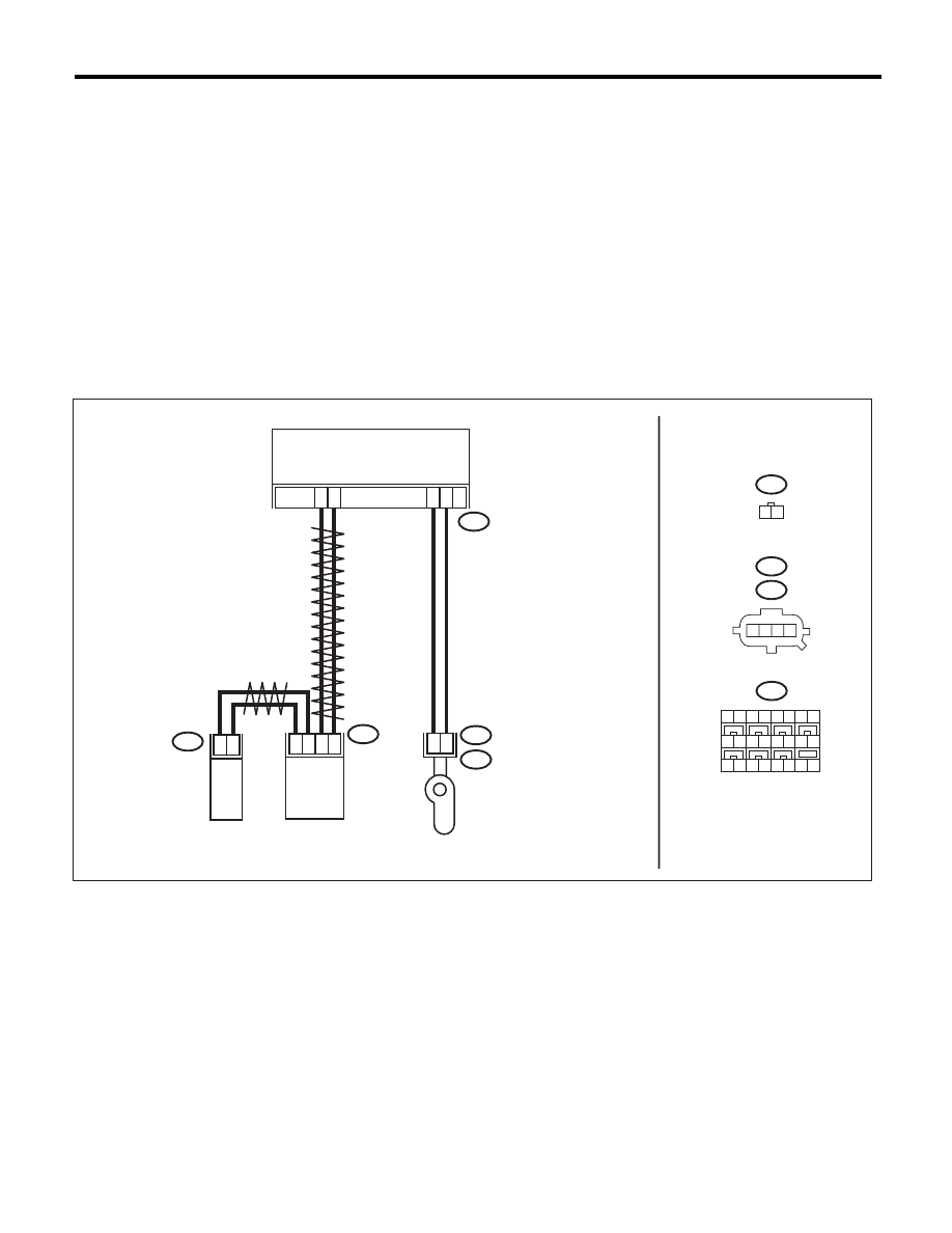
WIRING DIAGRAM:
AB18
AB24
AB25
1
2
17
18
AB28
8
7
3
4
1
2
AB18
AB28
AB-02105
3
4
AB34
AB34
18 19 20 21 22 23 24
1 2 3 4
11
10
12 13 14
16
17
15
1 2 3 4
1 2
AB24
AIRBAG CONTROL MODULE
CURTAIN AIRBAG
SENSOR RH
(C PILLAR)
SIDE AIRBAG
SENSOR RH
(B PILLAR)
SIDE AIRBAG
MODULE RH
8
7
6
5
9
AB(diag)-110
Diagnostic Chart with Trouble Code
AIRBAG SYSTEM (DIAGNOSTICS)
Step
Check
Yes
No
1
CHECK POOR CONTACT IN CONNECTORS.
Check for poor contact of the connectors
(AB18, AB28, AB34) between the airbag control
module and the curtain airbag sensor (RH).
Is there poor contact?
Replace the airbag
rear harness along
with body harness.
Go to step 2.
2
CHECK AIRBAG REAR HARNESS (BE-
TWEEN SIDE AIRBAG SENSOR RH AND
CURTAIN AIRBAG SENSOR RH).
1) Turn the ignition switch to OFF, disconnect
the battery ground cable, and wait for 20 sec-
onds or more.
2) Disconnect the connector (AB26) from seat
belt pretensioner (RH).
3) Disconnect the connector (AB33) from cur-
tain airbag module (RH).
4) Disconnect connectors (AB25) and (AB24)
from side airbag module (RH).
5) Disconnect connector (AB28) from side air-
bag sensor (RH).
6) Connect the connector (AB28) of side air-
bag sensor (RH) and the connector (1AI) in the
test harness AI.
7) Connect the connector (2AI) in the test har-
ness AI and the connector (1V) in the test har-
ness V.
8) Disconnect the connector (AB34) from cur-
tain airbag sensor (RH), and connect the con-
nector (2V) in test harness V to connector
(AB34).
9) Measure the resistance between connector
(3V) terminals in the test harness V.
Connector & terminal
(3V) No. 2 — (3V) No. 6:
(3V) No. 1 — (3V) No. 7:
Is the resistance less than 10
:? Go to step 3.
Replace the airbag
rear harness along
with body harness.
3
CHECK AIRBAG REAR HARNESS (BE-
TWEEN SIDE AIRBAG SENSOR AND CUR-
TAIN AIRBAG SENSOR RH).
Measure the resistance between connector
(3V) in test harness V and chassis ground, and
the resistance between connector (3V) in test
harness V.
Connector & terminal
(3V) No. 2 — Chassis ground:
(3V) No. 1 — Chassis ground:
(3V) No. 1 — (3V) No. 2:
Is the resistance 1 M
: or
more?
Go to step 4.
Replace the airbag
rear harness along
with body harness.

AB(diag)-111
Diagnostic Chart with Trouble Code
AIRBAG SYSTEM (DIAGNOSTICS)
4
CHECK AIRBAG REAR HARNESS (BE-
TWEEN AIRBAG CONTROL MODULE AND
SIDE AIRBAG SENSOR RH).
1) Disconnect the connectors (AB17, AB6,
AB18) from airbag control module.
2) Connect the connector (1AG) in the test har-
ness AG to the connectors (AB17, AB6, AB18).
3) Disconnect the connector (AB28) in the side
airbag sensor (RH) from the connector (1AI) in
the test harness AI.
4) Disconnect the connector (2AI) in the test
harness AI from the connector (1V) in the test
harness V.
5) Connect the connector (AB28) of side air-
bag sensor (RH) and the connector (2V) in the
test harness V to the connector (AB28).
6) Measure the resistance between connector
(5AG) in the test harness AG and connector
(3V) in the test harness V.
Connector & terminal
(5AG) No. 16 — (3V) No. 2:
(5AG) No. 14 — (3V) No. 1:
Is the resistance less than 10
:? Go to step 5.
Replace the airbag
rear harness along
with body harness.
5
CHECK AIRBAG REAR HARNESS (BE-
TWEEN AIRBAG CONTROL MODULE AND
SIDE AIRBAG SENSOR RH).
Measure the resistance between connector
(5AG) in the test harness AG and chassis
ground, and the resistance between connector
(5AG) in the test harness AG and connector
(3V) in test harness V.
Connector & terminal
(5AG) No. 16 — Chassis ground:
(5AG) No. 14 — Chassis ground:
(5AG) No. 14 — (5AG) No. 16:
Is the resistance 1 M
: or
more?
Go to step 6.
Replace the airbag
rear harness along
with body harness.
6
CHECK AIRBAG CONTROL MODULE.
1) Connect all connectors.
2) Clear the memory.
3) Perform the Inspection Mode.
4) Read the DTC.
Is the same DTC displayed?
Go to step 7.
Go to step 8.
7
REPLACE SIDE AIRBAG SENSOR (RH) AND
CHECK AIRBAG CONTROL MODULE AF-
TER REPLACEMENT.
<Ref. to AB-22, REMOVAL, Side Airbag Sen-
sor.>
1) Connect all connectors.
2) Clear the memory.
3) Perform the Inspection Mode.
4) Read the DTC.
Is the system normal?
Go to step 8.
Replace the cur-
tain airbag sensor
(RH). <Ref. to AB-
23, REMOVAL,
Curtain Airbag
Sensor.> Replace
the airbag control
module if not oper-
ating normally
even after replac-
ing the sensor.
<Ref. to AB-20,
REMOVAL, Airbag
Control Module.>
8
CHECK FOR ANY OTHER DTC ON DISPLAY. Is any other DTC displayed?
Check DTC using
“List of Diagnostic
Trouble Code
(DTC)”. <Ref. to
AB(diag)-38, List
of Diagnostic Trou-
ble Code (DTC).>
Finish the diagno-
sis.
Step
Check
Yes
No
Нет комментариевНе стесняйтесь поделиться с нами вашим ценным мнением.
Текст