Subaru Legacy IV (2008 year). Service manual — part 890
DS-5
General Description
DRIVE SHAFT SYSTEM
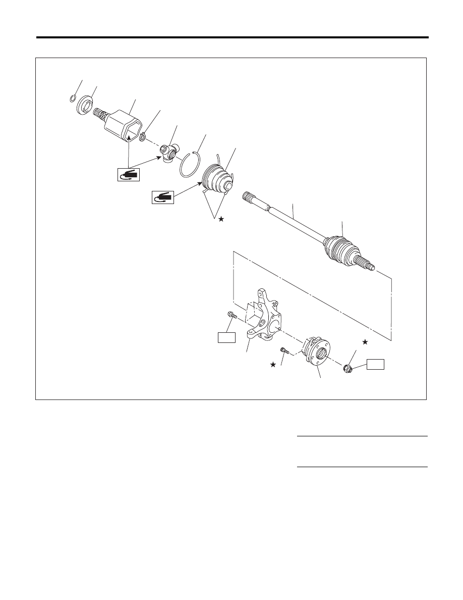
2. FRONT AXLE
(1)
Circlip
(7)
Boot band
(13)
Front hub unit bearing
(2)
Baffle plate
(8)
Boot (PTJ)
(14)
Axle nut
(3)
Outer race (PTJ)
(9)
Boot (EBJ)
(4)
Snap ring
(10)
EBJ shaft ASSY
Tightening torque:N·m (kgf-m, ft-lb)
(5)
Trunnion
(11)
Housing
T1: 220 (22.4, 162)
(6)
Snap ring
(12)
Hub bolt
T2: 65 (6.6, 47.9)
(3)
(2)
(1)
(13)
(4)
(5)
(14)
(9)
(10)
(12)
(7)
(6)
(11)
T2
T1
(8)
DS-00232
DS-6
General Description
DRIVE SHAFT SYSTEM
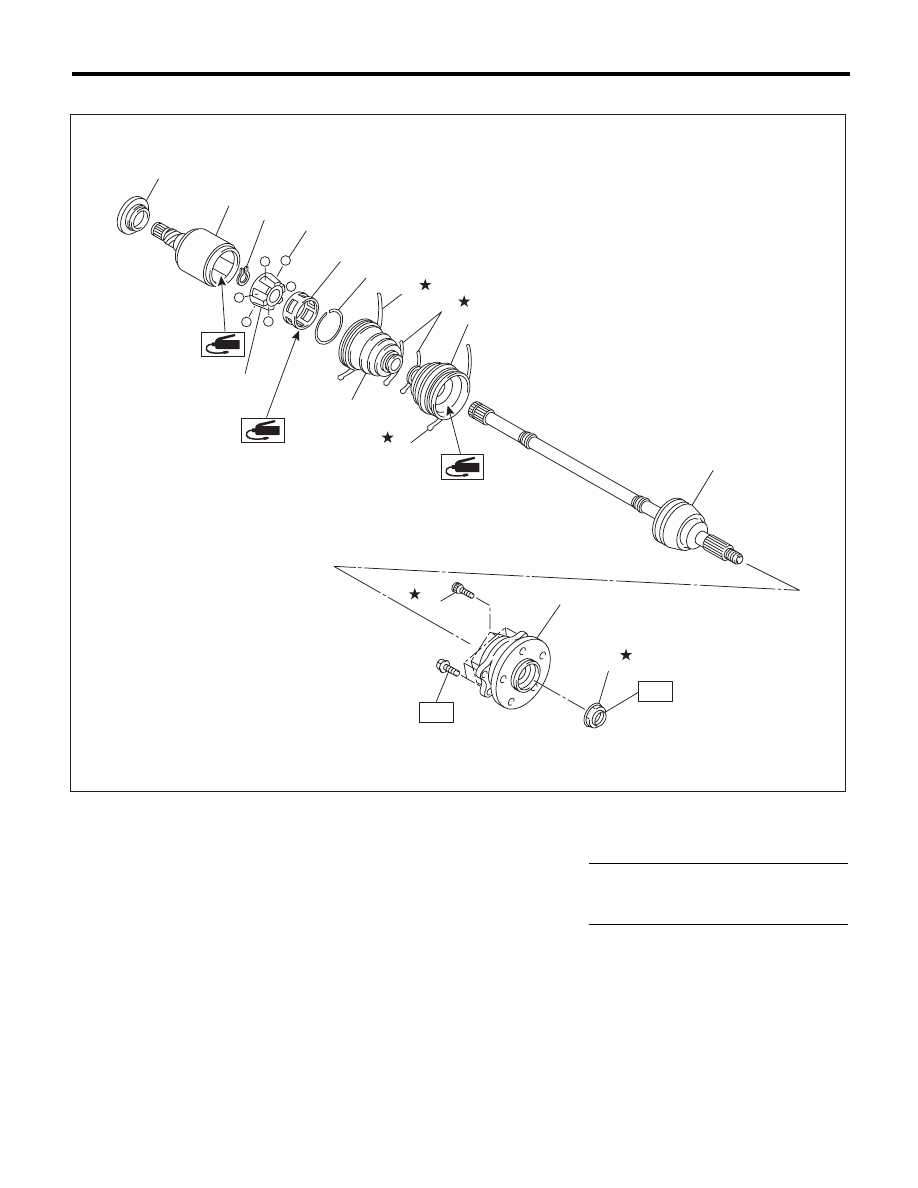
3. REAR AXLE
(1)
Baffle plate (DOJ)
(8)
Boot band
(13)
Hub bolt
(2)
Outer race (DOJ)
(9)
Boot (DOJ)
(14)
Axle nut
(3)
Snap ring
(10)
Boot (BJ)
(4)
Inner race
(11)
BJ shaft ASSY (2.5 i AT model)
Tightening torque:N·m (kgf-m, ft-lb)
(5)
Ball
EBJ shaft ASSY (Except for 2.5 i
AT model)
T1: 65 (6.6, 47.9)
(6)
Cage
T2: 240 (24.5, 177)
(7)
Snap ring
(12)
Rear hub unit bearing
DS-00233
(13)
(12)
T1
(5)
(4)
(6)
(3)
(2)
(1)
(11)
(10)
(9)
(8)
(8)
(8)
(7)
(14)
T2
DS-7
General Description
DRIVE SHAFT SYSTEM
C: CAUTION
• Wear appropriate work clothing, including a cap,
protective goggles and protective shoes when per-
forming any work.
• Remove contamination including dirt and corro-
sion before removal, installation or disassembly.
• Keep the disassembled parts in order and pro-
tect them from dust and dirt.
• Before removal, installation or disassembly, be
sure to clarify the failure. Avoid unnecessary re-
moval, installation, disassembly and replacement.
• Vehicle components are extremely hot after driv-
ing. Be wary of receiving burns from heated parts.
• Use SUBARU genuine grease etc. or equivalent.
Do not mix grease etc. of different grades or man-
ufacturers.
• Be sure to tighten fasteners including bolts and
nuts to the specified torque.
• Place shop jacks or rigid racks at the specified
points.
• Apply grease onto sliding or revolving surfaces
before installation.
• Before installing snap rings, apply sufficient
amount of grease to avoid damage and deforma-
tion.
• Before securing a part on a vise, place cushion-
ing materials such as wood blocks, aluminum
plates, or waste cloth between the part and the
vise.
DS-8
General Description
DRIVE SHAFT SYSTEM
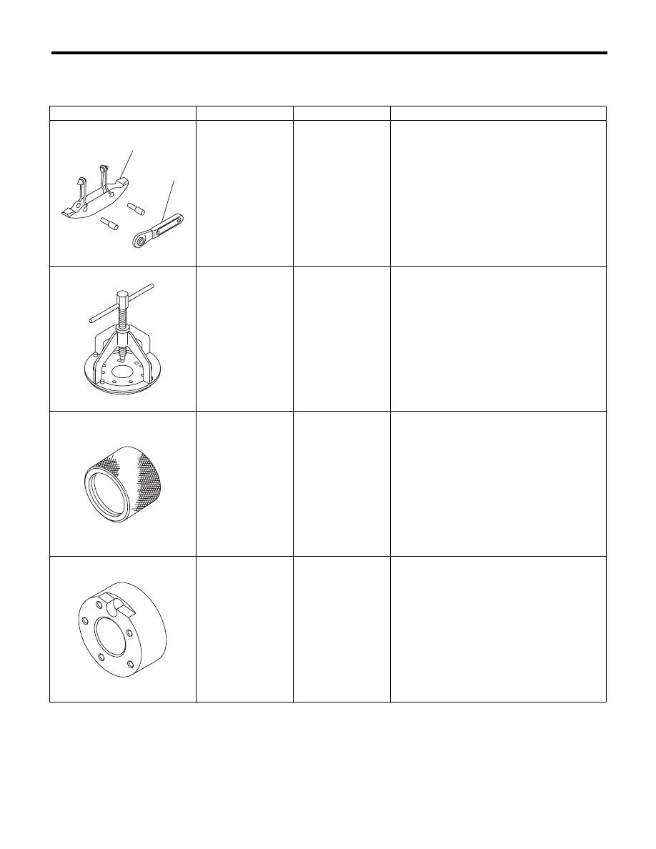
D: PREPARATION TOOL
1. SPECIAL TOOL
ILLUSTRATION
TOOL NUMBER
DESCRIPTION
REMARKS
925091000
BAND TIGHTENING
TOOL
Used for tightening the boot band.
(A) Jig for the band
(B) Ratchet wrench
926470000
AXLE SHAFT
PULLER
• Used for removing the axle shaft.
• Used together with the AXLE SHAFT PULLER
PLATE (28099PA110).
18675AA000
DIFFERENTIAL
SIDE OIL SEAL
INSTALLER
Used for installing the differential side retainer oil
seal.
927080000
HUB STAND
Used for assembling hub bolt in hub.
ST-925091000
(A)
(B)
ST-926470000
ST18675AA000
ST-927080000
Нет комментариевНе стесняйтесь поделиться с нами вашим ценным мнением.
Текст