Subaru Legacy IV (2008 year). Service manual — part 237
FU(H4DOTC)-51
SI-DRIVE (SUBARU Intelligent Drive) S# Switch
FUEL INJECTION (FUEL SYSTEMS)
20.SI-DRIVE (SUBARU Intelligent
Drive) S# Switch
A: REMOVAL
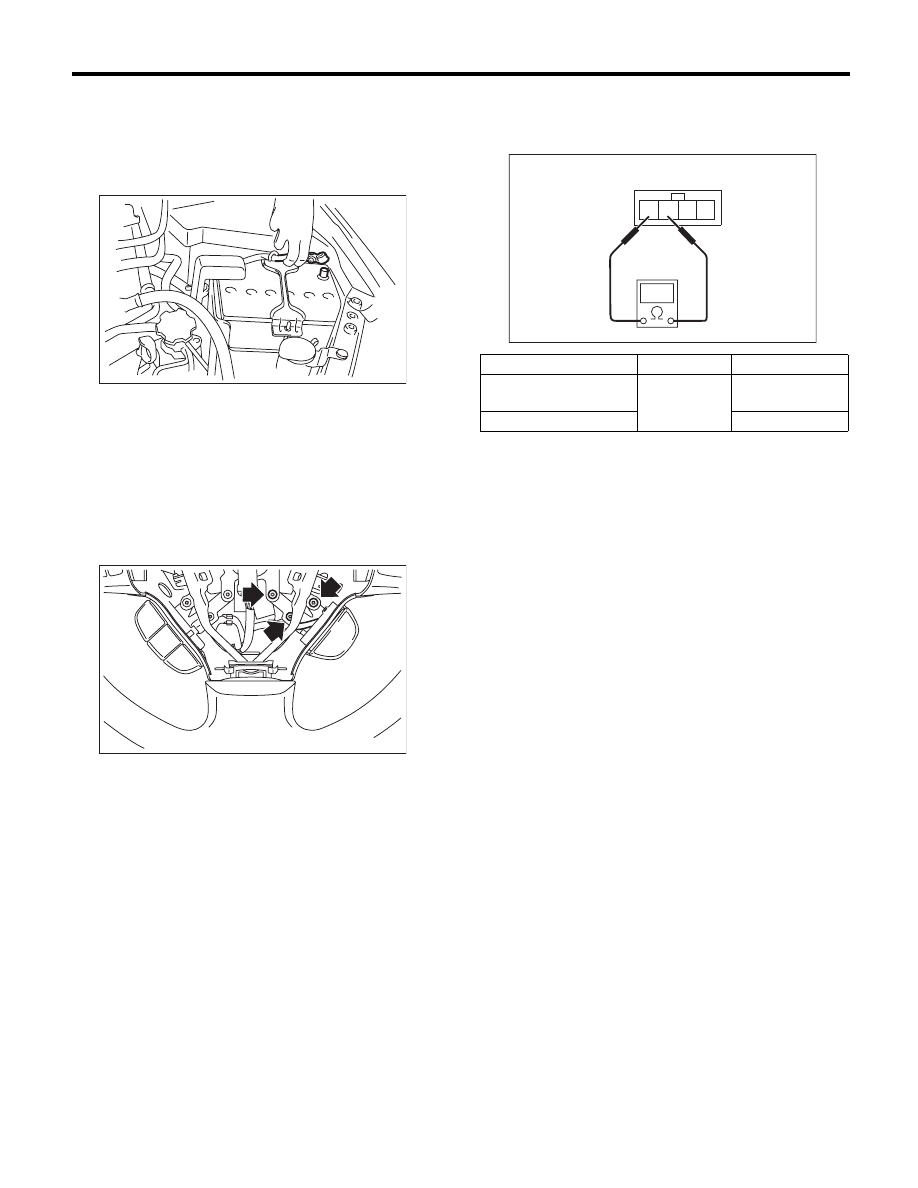
1) Disconnect the ground cable from battery.
2) Remove the airbag module. <Ref. to AB-14, RE-
MOVAL, Driver’s Airbag Module.>
WARNING:
Always refer to “Airbag System” before per-
forming service on the airbag modules. <Ref. to
AB-4, CAUTION, General Description.>
3) Remove the screws which secure the SI-DRIVE
S# switch to the steering wheel, and remove the SI-
DRIVE S# switch.
4) Disconnect the connectors from the SI-DRIVE
S# switch.
B: INSTALLATION
Install in the reverse order of removal.
C: INSPECTION
Measure the resistance between SI-DRIVE S#
switch terminals.
IN-00203
FU-03122
Switch position
Terminal No.
Standard value
ON (When the SI-DRIVE
S# switch is pressed)
3 and 4
Less than 10
:
OFF
1 M
: or more
2
3
4
1
FU-03121
FU(H4DOTC)-52
Engine Control Module (ECM)
FUEL INJECTION (FUEL SYSTEMS)
21.Engine Control Module (ECM)
A: REMOVAL
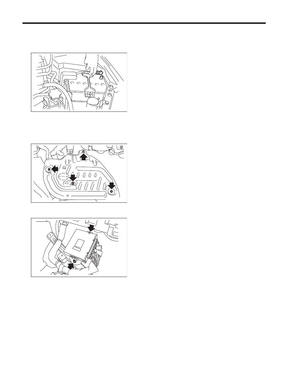
1) Disconnect the ground cable from battery.
2) Remove the lower inner trim of passenger’s
side.
<Ref. to EI-61, REMOVAL, Lower Inner Trim.>
3) Detach the floor mat of passenger’s seat.
4) Remove the protect cover.
5) Remove the nuts and bolts which hold the ECM
to the bracket.
6) Disconnect the ECM connectors, and take out
the ECM.
B: INSTALLATION
Install in the reverse order of removal.
CAUTION:
When the ECM of model with immobilizer has
been replaced, be sure to perform the registra-
tion of immobilizer system. (Refer to the “PC
application help for Subaru Select Monitor”.)
NOTE:
When replacing the ECM, be careful not to use the
wrong spec. ECM to avoid any damage on the fuel
injection system.
Tightening torque:
7.5 N·m (0.8 kgf-m, 5.5 ft-lb)
IN-00203
FU-03416
FU-03417
FU(H4DOTC)-53
Main Relay
FUEL INJECTION (FUEL SYSTEMS)
22.Main Relay
A: REMOVAL
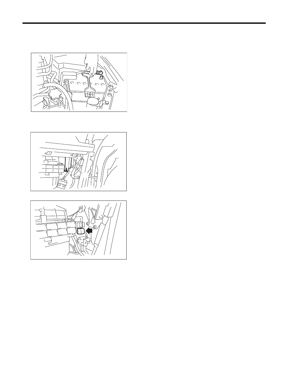
1) Disconnect the ground cable from battery.
2) Remove the glove box. <Ref. to EI-52, REMOV-
AL, Glove Box.>
3) Remove the harness cover (A).
4) Disconnect the connectors from main relay.
B: INSTALLATION
Install in the reverse order of removal.
IN-00203
FU-02092
(A)
FU-02093
FU(H4DOTC)-54
Fuel Pump Relay
FUEL INJECTION (FUEL SYSTEMS)
23.Fuel Pump Relay
A: REMOVAL
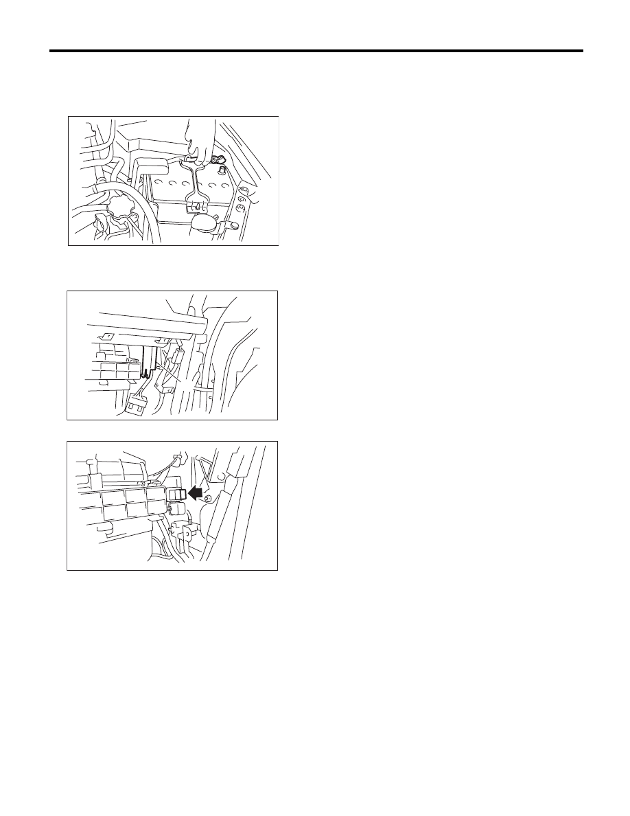
1) Disconnect the ground cable from battery.
2) Remove the glove box. <Ref. to EI-52, REMOV-
AL, Glove Box.>
3) Remove the harness cover (A).
4) Disconnect the connector from fuel pump relay.
B: INSTALLATION
Install in the reverse order of removal.
IN-00203
FU-02092
(A)
FU-02094
Нет комментариевНе стесняйтесь поделиться с нами вашим ценным мнением.
Текст