Subaru Legacy IV (2008 year). Service manual — part 542
EN(H6DO)(diag)-141
Diagnostic Procedure with Diagnostic Trouble Code (DTC)
ENGINE (DIAGNOSTICS)
AC:DTC P0113 INTAKE AIR TEMPERATURE SENSOR 1 CIRCUIT HIGH
DTC DETECTING CONDITION:
• Immediately at fault recognition
• GENERAL DESCRIPTION <Ref. to GD(H6DO)-40, DTC P0113 INTAKE AIR TEMPERATURE SENSOR
1 CIRCUIT HIGH, Diagnostic Trouble Code (DTC) Detecting Criteria.>
TROUBLE SYMPTOM:
• Improper idling
• Poor driving performance
CAUTION:
After repair or replacement of faulty parts, perform Clear Memory Mode <Ref. to EN(H6DO)(diag)-52,
OPERATION, Clear Memory Mode.>, and Inspection Mode <Ref. to EN(H6DO)(diag)-44, PROCEDURE,
Inspection Mode.>.
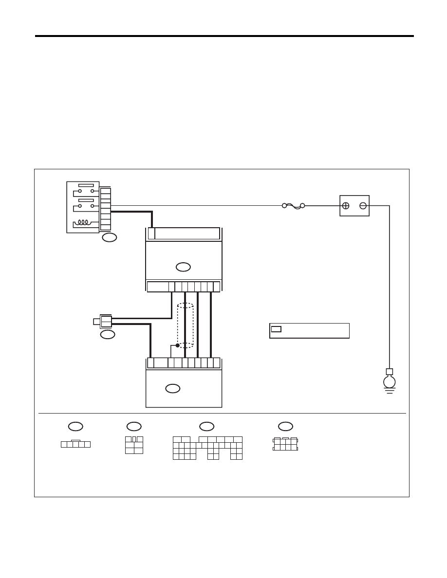
WIRING DIAGRAM:
EN-03920
B83
B3
BATTERY
E
B83
1
B3
MASS AIR FLOW & INTAKE
AIR TEMPERATURE SENSOR
ECM
B135
SBF-7
1 2 3 4 5
3
4
1
2
5
6
B135
B47
*
*
2
4
3
5
34
18
26
30
35
MAIN RELAY
B47
1
2
4
6
3
5
1 2 3 4
5 6 7 8
*
: TERMINAL No.
OPTIONAL ARRANGEMENT
5
6
7
8
2
1
9
4
3
10
24
22 23
25
11 12 13 14 15
26 27
28
16 17 18 19
20 21
29 30 31
32 33
34 35

EN(H6DO)(diag)-142
Diagnostic Procedure with Diagnostic Trouble Code (DTC)
ENGINE (DIAGNOSTICS)
Step
Check
Yes
No
1
CHECK CURRENT DATA.
1) Start the engine.
2) Read the data of intake air temperature sen-
sor signal using Subaru Select Monitor or gen-
eral scan tool.
NOTE:
• SUBARU SELECT MONITOR
For detailed operation procedure, refer to
“READ CURRENT DATA FOR ENGINE”. <Ref.
to EN(H6DO)(diag)-34, Subaru Select Moni-
tor.>
• General Scan Tool
For detailed operation procedures, refer to the
general scan tool operation manual.
Is the intake air temperature
less than –40°C (–40°F) ?
Go to step 2.
Even if DTC is
detected, the cir-
cuit has returned to
a normal condition
at this time. Repro-
duce the failure,
and then perform
the diagnosis
again.
NOTE:
In this case, tem-
porary poor con-
tact of connector
may be the cause.
2
CHECK POOR CONTACT.
Check for poor contact in the ECM or the mass
air flow and intake air temperature sensor con-
nector.
Is there poor contact in the
ECM or the mass air flow and
intake air temperature sensor
connector?
Repair any poor
contact in the ECM
or the mass air flow
and intake air tem-
perature sensor
connector.
Go to step 3.
3
CHECK HARNESS BETWEEN ECM AND
MASS AIR FLOW AND INTAKE AIR TEM-
PERATURE SENSOR CONNECTOR.
1) Turn the ignition switch to OFF.
2) Disconnect the connector from ECM and
mass air flow and intake air temperature sensor.
3) Measure the resistance of harness between
ECM and mass air flow and intake air tempera-
ture sensor connectors.
Connector & terminal
(B135) No. 18 — (B3) No. 4:
(B135) No. 30 — (B3) No. 5:
Is the resistance less than 1
:? Go to step 4.
Repair the open
circuit of harness
between ECM and
mass air flow and
intake air tempera-
ture sensor con-
nector.
4
CHECK HARNESS BETWEEN ECM AND
MASS AIR FLOW AND INTAKE AIR TEM-
PERATURE SENSOR CONNECTOR.
1) Connect all connectors.
2) Turn the ignition switch to ON.
3) Disconnect the connector from the mass air
flow and intake air temperature sensor.
4) Measure the voltage between ECM and
chassis ground.
Connector & terminal
(B135) No. 18 (+) — Chassis ground (–):
Is the voltage 5 V or more?
Repair the short
circuit to power in
the harness
between the ECM
and the mass air
flow and intake air
temperature sen-
sor connector.
Replace the mass
air flow and intake
air temperature
sensor. <Ref. to
FU(H6DO)-26,
Mass Air Flow and
Intake Air Temper-
ature Sensor.>
EN(H6DO)(diag)-143
Diagnostic Procedure with Diagnostic Trouble Code (DTC)
ENGINE (DIAGNOSTICS)
AD:DTC P0117 ENGINE COOLANT TEMPERATURE CIRCUIT LOW
DTC DETECTING CONDITION:
• Immediately at fault recognition
• GENERAL DESCRIPTION <Ref. to GD(H6DO)-41, DTC P0117 ENGINE COOLANT TEMPERATURE
CIRCUIT LOW, Diagnostic Trouble Code (DTC) Detecting Criteria.>
TROUBLE SYMPTOM:
• Hard to start
• Improper idling
• Poor driving performance
CAUTION:
After repair or replacement of faulty parts, perform Clear Memory Mode <Ref. to EN(H6DO)(diag)-52,
OPERATION, Clear Memory Mode.>, and Inspection Mode <Ref. to EN(H6DO)(diag)-44, PROCEDURE,
Inspection Mode.>.
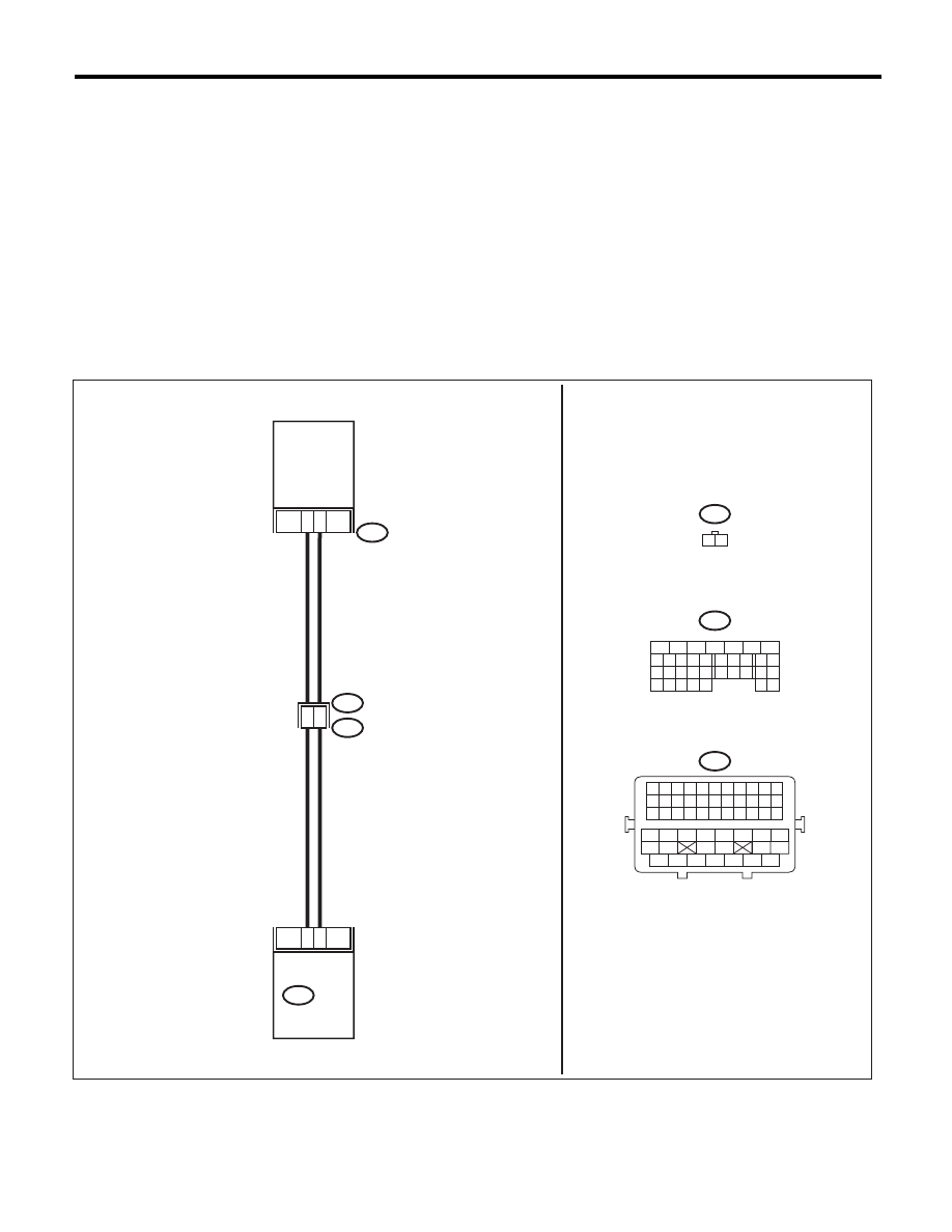
WIRING DIAGRAM:
EN-06872
29
34
19
8
B134
ECM
1
2
E2
B21
E8
ENGINE
COOLANT
TEMPERATURE
SENSOR
B134
5
6
7
8
2
1
9
4
3
10
24
22 23
25
11 12 13 14 15
26 27
28
16 17
18 19 20 21
33 34
29
32
30 31
E8
1 2
B21
1 2 3 4 5 6 7 8 9 10 11
12 13 14 15 16 17 18 19 20 21 22
23 24 25 26 27 28 29 30 31 32 33
34
35
42
43
36
37
38
39
48
49
50
51
52
53
54
40
41
44
45
46
47

EN(H6DO)(diag)-144
Diagnostic Procedure with Diagnostic Trouble Code (DTC)
ENGINE (DIAGNOSTICS)
Step
Check
Yes
No
1
CHECK CURRENT DATA.
1) Start the engine.
2) Read the data of engine coolant tempera-
ture sensor signal using Subaru Select Monitor
or general scan tool.
NOTE:
• SUBARU SELECT MONITOR
For detailed operation procedure, refer to
“READ CURRENT DATA FOR ENGINE”. <Ref.
to EN(H6DO)(diag)-34, Subaru Select Moni-
tor.>
• General Scan Tool
For detailed operation procedures, refer to the
general scan tool operation manual.
Is the engine coolant tempera-
ture 150°C (302°F) or higher?
Go to step 2.
Even if DTC is
detected, the cir-
cuit has returned to
a normal condition
at this time. Repro-
duce the failure,
and then perform
the diagnosis
again.
NOTE:
In this case, tem-
porary poor con-
tact of connector
may be the cause.
2
CHECK HARNESS BETWEEN ECM AND EN-
GINE COOLANT TEMPERATURE SENSOR
CONNECTOR.
1) Turn the ignition switch to OFF.
2) Disconnect the connectors from ECM and
engine coolant temperature sensor.
3) Measure the resistance between ECM and
chassis ground.
Connector & terminal
(B134) No. 34 — Chassis ground:
Is the resistance 1 M
: or
more?
Replace the
engine coolant
temperature sen-
sor. <Ref. to
FU(H6DO)-20,
Engine Coolant
Temperature Sen-
sor.>
Repair the short
circuit to ground in
harness between
ECM and engine
coolant tempera-
ture sensor.
Нет комментариевНе стесняйтесь поделиться с нами вашим ценным мнением.
Текст