Subaru Legacy IV (2008 year). Service manual — part 532
EN(H6DO)(diag)-101
Diagnostic Procedure with Diagnostic Trouble Code (DTC)
ENGINE (DIAGNOSTICS)
I:
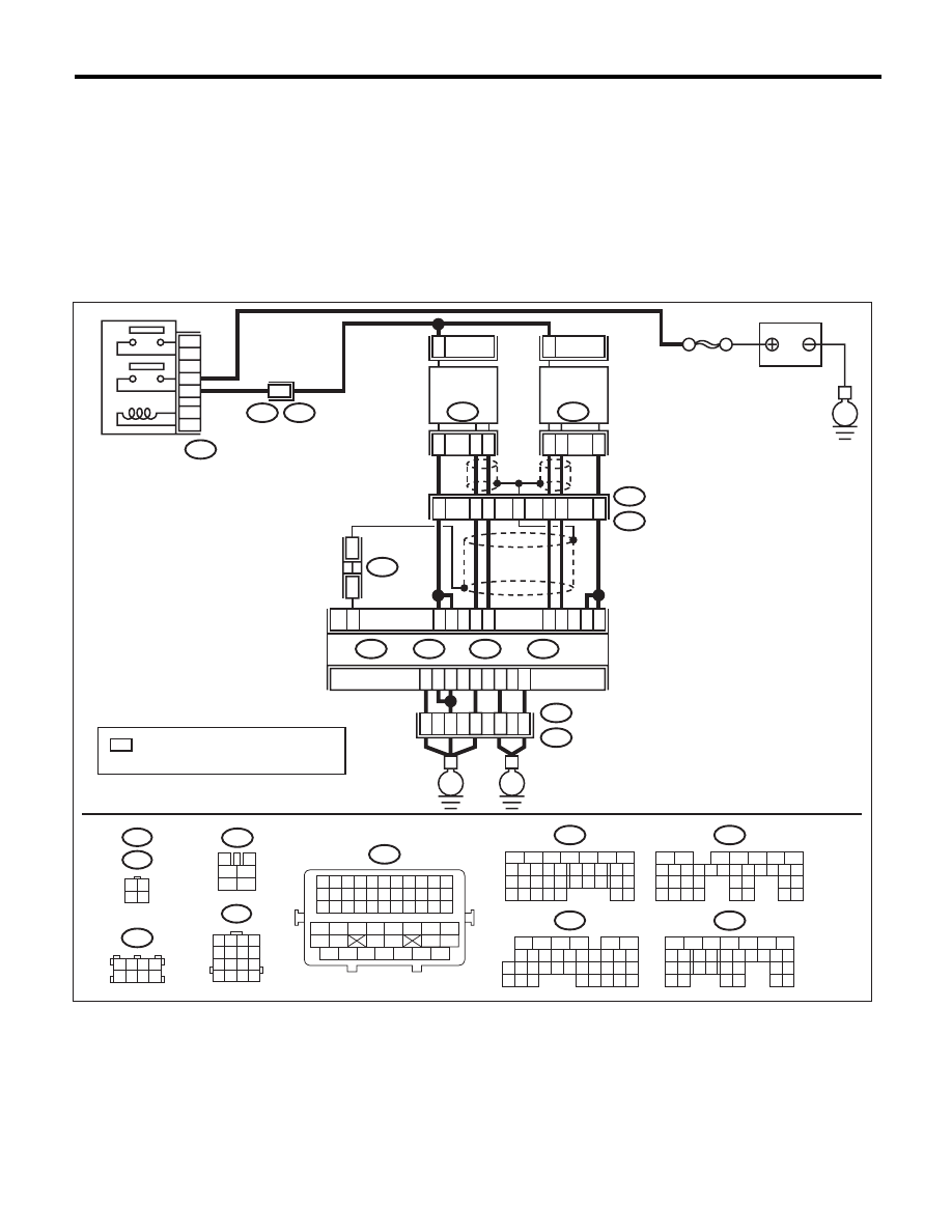
DTC P0032 HO2S HEATER CONTROL CIRCUIT HIGH (BANK 1 SENSOR 1)
DTC DETECTING CONDITION:
• Immediately at fault recognition
• GENERAL DESCRIPTION <Ref. to GD(H6DO)-21, DTC P0032 HO2S HEATER CONTROL CIRCUIT
HIGH (BANK 1 SENSOR 1), Diagnostic Trouble Code (DTC) Detecting Criteria.>
CAUTION:
After repair or replacement of faulty parts, perform Clear Memory Mode <Ref. to EN(H6DO)(diag)-52,
OPERATION, Clear Memory Mode.>, and Inspection Mode <Ref. to EN(H6DO)(diag)-44, PROCEDURE,
Inspection Mode.>.
WIRING DIAGRAM:
SBF-5
BATTERY
E
E3
B22
B47
1
2
3
5
4
6
MAIN RELAY
E3
B22
8
: TERMINAL No. OPTIONAL ARRANGEMENT
AMONG 1, 2, 5 AND 6
*
3
4
5
6
1
2
B47
1 2 3 4
5 6 7 8
9 10 11 12
13 14 15 16
B22
3 4
1 2
E47
E24
16
10 11 12 13 14 15
25
24
30
9
8
7
17 18 19 20
28
21 22 23
29
32
31
1
2
3
4
5
6
27
26
33 34 35
B136
C:
5
6
7
8
2
1
9
4
3
10
22 23
11 12 13 14 15
24 25
26
16 17
18 19 20 21
27
28 29
30 31
B137
D:
1 2 3 4
5 6 7 8
B138
5
6
7
8
2
1
9
4
3
10
24
22 23
25
11 12 13 14 15
26 27
28
16 17 18 19
20 21
29 30 31
32 33
34 35
B135
B:
5
6
7
8
2
1
9
4
3
10
24
22 23
25
11 12 13 14 15
26 27
28
16 17
18 19 20 21
33 34
29
32
30 31
B134
A:
B11
2
E24
FRONT
OXYGEN (A/F)
SENSOR LH
3
4
B10
1
B7
B6
C2
C3
B8
4
1
3
B9
ECM
B135
B:
B134
A:
B137
D:
B136
C:
D3
A3
D2
D1
D7
A5
35
34
52
36
37
B21
E2
E
E
EN-06867
B21
1 2 3 4 5 6 7 8 9 10 11
12 13 14 15 16 17 18 19 20 21 22
23 24 25 26 27 28 29 30 31 32 33
34
35
42
43
36
37
38
39
48
49
50
51
52
53
54
40
41
44
45
46
47
2
E47
FRONT
OXYGEN (A/F)
SENSOR RH
5
6
7
4
2
1
3
B138
*
*
B1

EN(H6DO)(diag)-102
Diagnostic Procedure with Diagnostic Trouble Code (DTC)
ENGINE (DIAGNOSTICS)
Step
Check
Yes
No
1
CHECK HARNESS BETWEEN ECM AND
FRONT OXYGEN (A/F) SENSOR.
1) Turn the ignition switch to OFF.
2) Measure the voltage between ECM and
chassis ground.
Connector & terminal
(B136) No. 2 (+) — Chassis ground (–):
(B136) No. 3 (+) — Chassis ground (–):
Is the voltage 10 V or more?
Repair the short
circuit to power in
the harness
between ECM and
front oxygen (A/F)
sensor connector.
Go to step 2.
2
CHECK GROUND CIRCUIT FOR ECM.
1) Disconnect the connectors from ECM.
2) Measure the resistance between ECM and
chassis ground.
Connector & terminal
(B134) No. 3 — Chassis ground:
(B134) No. 5 — Chassis ground:
(B137) No. 1 — Chassis ground:
(B137) No. 2 — Chassis ground:
(B137) No. 3 — Chassis ground:
(B137) No. 7 — Chassis ground:
Is the resistance less than 5
:? Repair the poor
contact of ECM
connector.
Repair the harness
and connector.
NOTE:
In this case, repair
the following item:
• Open circuit of
harness between
ECM and engine
ground
• Poor contact of
coupling connector
EN(H6DO)(diag)-103
Diagnostic Procedure with Diagnostic Trouble Code (DTC)
ENGINE (DIAGNOSTICS)
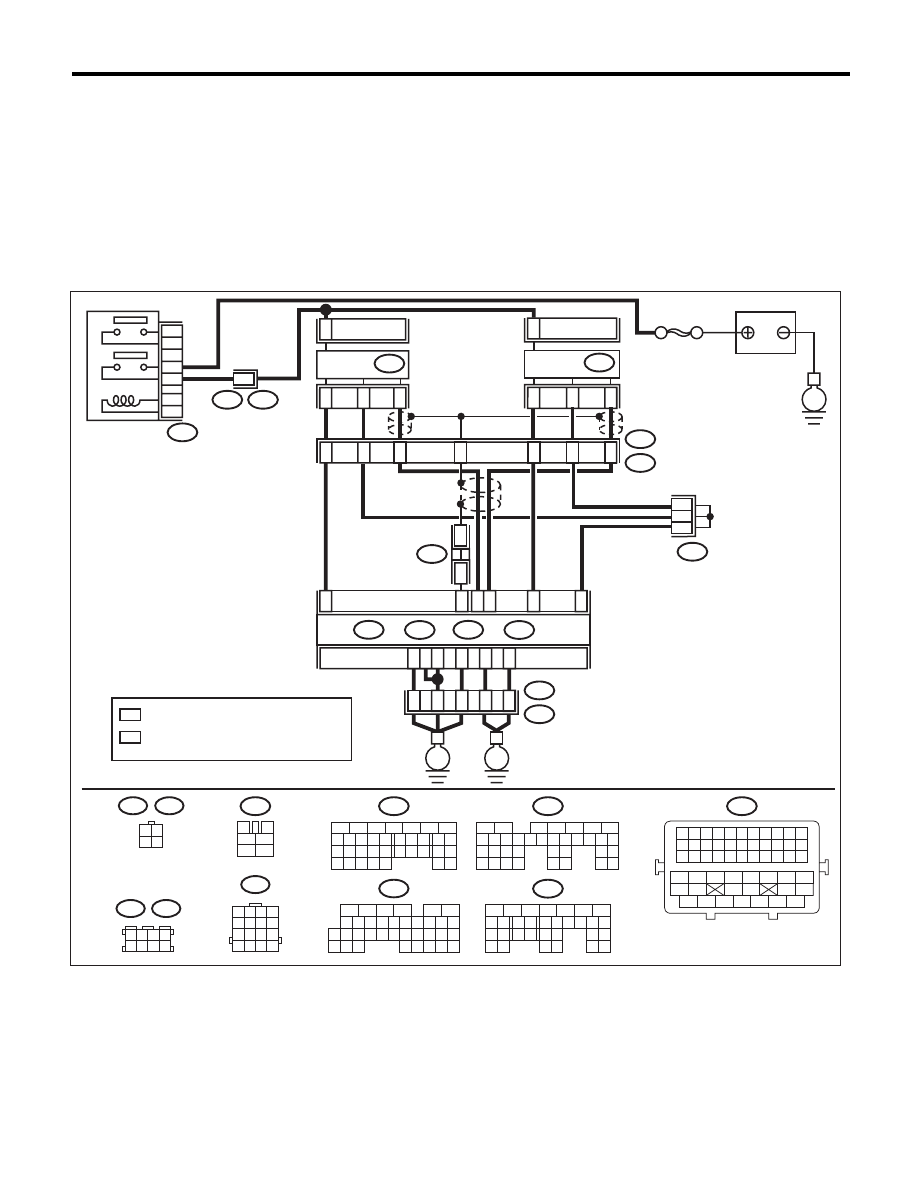
J: DTC P0037 HO2S HEATER CONTROL CIRCUIT LOW (BANK 1 SENSOR 2)
DTC DETECTING CONDITION:
• Two consecutive driving cycles with fault
• GENERAL DESCRIPTION <Ref. to GD(H6DO)-23, DTC P0037 HO2S HEATER CONTROL CIRCUIT
LOW (BANK 1 SENSOR 2), Diagnostic Trouble Code (DTC) Detecting Criteria.>
CAUTION:
After repair or replacement of faulty parts, perform Clear Memory Mode <Ref. to EN(H6DO)(diag)-52,
OPERATION, Clear Memory Mode.>, and Inspection Mode <Ref. to EN(H6DO)(diag)-44, PROCEDURE,
Inspection Mode.>.
WIRING DIAGRAM:
B47
3
4
5
6
1
2
B22
1 2 3 4
5 6 7 8
9 10 11 12
13 14 15 16
1 2 3 4
5 6 7 8
B83
B138
3 4
1 2
E25
E61
B47
1
2
3
5
4
6
E3
B22
14
MAIN RELAY
2
4
3
1
E25
13
15
16
E3
B22
10
11
12
9
SBF-5
BATTERY
2
E61
4
3
1
*
1
*
1
*
1
B83
B138
ECM
B134
A:
B135
B:
B136
C:
B137
D3
A3
D2
D1
D7
A5
D:
C5
*
*
2
2
C4
E
B1
B15
B4
B30
35
34
52
36
37
B21
E2
E
E
: TERMINAL No. OPTIONAL ARRANGEMENT
*
1
: TERMINAL No. OPTIONAL ARRANGEMENT
AMONG 1, 2, 5 AND 6
*
2
EN-06868
16
10 11 12 13 14 15
25
24
30
9
8
7
17 18 19 20
28
21 22 23
29
32
31
1
2
3
4
5
6
27
26
33 34 35
B136
C:
5
6
7
8
2
1
9
4
3
10
22 23
11 12 13 14 15
24 25
26
16 17
18 19 20 21
27
28 29
30 31
B137
D:
5
6
7
8
2
1
9
4
3
10
24
22 23
25
11 12 13 14 15
26 27
28
16 17 18 19
20 21
29 30 31
32 33
34 35
B135
B:
5
6
7
8
2
1
9
4
3
10
24
22 23
25
11 12 13 14 15
26 27
28
16 17
18 19 20 21
33 34
29
32
30 31
B134
A:
B21
1 2 3 4 5 6 7 8 9 10 11
12 13 14 15 16 17 18 19 20 21 22
23 24 25 26 27 28 29 30 31 32 33
34
35
42
43
36
37
38
39
48
49
50
51
52
53
54
40
41
44
45
46
47
REAR
OXYGEN
SENSOR LH
REAR
OXYGEN
SENSOR RH

EN(H6DO)(diag)-104
Diagnostic Procedure with Diagnostic Trouble Code (DTC)
ENGINE (DIAGNOSTICS)
Step
Check
Yes
No
1
CHECK POWER SUPPLY TO REAR OXY-
GEN SENSOR.
1) Turn the ignition switch to OFF.
2) Disconnect the connector from rear oxygen
sensor.
3) Turn the ignition switch to ON.
4) Measure the voltage between rear oxygen
sensor connector and engine ground.
Connector & terminal
(E61) No. 2 (+) — Engine ground (–):
Is the voltage 10 V or more?
Go to step 2.
Repair the power
supply line.
NOTE:
In this case, repair
the following item:
• Open circuit of
harness between
main relay and rear
oxygen sensor
• Poor contact of
main relay connec-
tor
• Poor contact of
coupling connector
• Malfunction of
main relay
2
CHECK HARNESS BETWEEN ECM AND
REAR OXYGEN SENSOR.
1) Turn the ignition switch to OFF.
2) Disconnect the connectors from ECM.
3) Measure the resistance between the ECM
and oxygen sensor connector.
Connector & terminal
(B136) No. 4 — (E61) No. 1:
Is the resistance less than 1
:? Go to step 3.
Repair the harness
and connector.
NOTE:
In this case, repair
the following item:
• Open circuit in
harness between
ECM and rear oxy-
gen sensor con-
nector
• Poor contact of
coupling connector
3
CHECK GROUND CIRCUIT FOR ECM.
Measure the resistance of harness between
ECM and chassis ground.
Connector & terminal
(B134) No. 3 — Chassis ground:
(B134) No. 5 — Chassis ground:
(B137) No. 1 — Chassis ground:
(B137) No. 2 — Chassis ground:
(B137) No. 3 — Chassis ground:
(B137) No. 7 — Chassis ground:
Is the resistance less than 5
:? Go to step 4.
Repair the harness
and connector.
NOTE:
In this case, repair
the following item:
• Open circuit of
harness between
ECM and engine
ground
• Poor contact of
coupling connector
4
CHECK REAR OXYGEN SENSOR.
Measure the resistance between rear oxygen
sensor connector terminals.
Terminals
No. 2 — No. 1:
Is the resistance between 5 —
7
:?
Repair the poor
contact of ECM
connector.
Replace the rear
oxygen sensor.
<Ref. to
FU(H6DO)-34,
Rear Oxygen Sen-
sor.>
Нет комментариевНе стесняйтесь поделиться с нами вашим ценным мнением.
Текст