Subaru Legacy IV (2008 year). Service manual — part 770
5AT(diag)-95
Diagnostic Procedure with Diagnostic Trouble Code (DTC)
AUTOMATIC TRANSMISSION (DIAGNOSTICS)
AH:DTC P1718 AT CAN COMMUNICATION CIRCUIT
NOTE:
DTC P1718 AT CAN communication circuit, refer to “LAN System”. <Ref. to LAN(diag)-12, READ DIAGNOS-
TIC TROUBLE CODE (DTC), OPERATION, Subaru Select Monitor.>
5AT(diag)-96
Diagnostic Procedure with Diagnostic Trouble Code (DTC)
AUTOMATIC TRANSMISSION (DIAGNOSTICS)
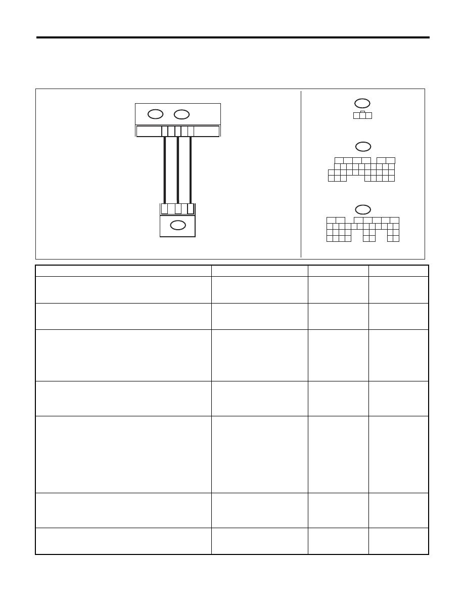
AI: DTC P1760 LATERAL ACCELERATION SENSOR PERFORMANCE PROBLEM
DTC DETECTING CONDITION:
Lateral G sensor output voltage fault
WIRING DIAGRAM:
Step
Check
Yes
No
1
CHECK VEHICLE CONDITION.
Is the vehicle a model with
VDC, which has the VDC OFF
switch on the instrument panel?
Go to step 2.
Go to step 4.
2
CHECK DTC OF TCM.
Is DTC of AT CAN communica-
tion detected?
Perform the diag-
nosis according to
DTC.
Go to step 3.
3
CHECK DTC OF ABS.
Is DTC of ABS detected?
Perform the diag-
nosis according to
DTC of ABS.
Temporary poor
contact occurs.
Recheck for defec-
tive parts in har-
ness and
connectors.
4
CHECK OUTPUT OF LATERAL G SENSOR
USING SUBARU SELECT MONITOR.
Read the value of “Lateral G Sensor” using
Subaru Select Monitor.
Is the reading indicated on
monitor display 2.3 to 2.7 V?
Go to step 5.
Go to step 10.
5
CHECK OUTPUT OF LATERAL G SENSOR
USING SUBARU SELECT MONITOR.
1) Turn the ignition switch to OFF.
2) Remove the console box.
3) Remove the lateral G sensor from vehicle.
(Do not disconnect the connector.)
4) Turn the ignition switch to ON.
5) Read the value of “Lateral G Sensor” using
Subaru Select Monitor.
Is the value on the display 3.3 —
4.3 V with the lateral G sensor
inclined 90° to right?
Go to step 6.
Replace the lateral
G sensor. <Ref. to
5AT-61, Lateral G
Sensor.>
6
CHECK OUTPUT OF LATERAL G SENSOR
USING SUBARU SELECT MONITOR.
Read the value of “Lateral G Sensor” using
Subaru Select Monitor.
Is the value on the display 0.7 —
1.7 V with the lateral G sensor
inclined 90° to left?
Go to step 7.
Replace the lateral
G sensor. <Ref. to
5AT-61, Lateral G
Sensor.>
7
CHECK POOR CONTACT IN CONNECTOR.
Turn the ignition switch to OFF.
Is there poor contact in connec-
tor between TCM and lateral G
sensor?
Repair the connec-
tor.
Go to step 8.
AT-04479
2
1
3
B359
B7
B9
B55
B:
TCM
B359
1 2 3
B:
B55
5
6
7
2
1
3
4
29
10 11 12 13 14 15
25
24
16
30
9
8
17 18 19
20
28
21 22 23
32
31
26 27
33
34 35
A:
B54
16
10 11 12 13 14 15
25
24
30
9
8
7
17 18 19 20
28
21 22 23
29
32
31
1
2
3
4
5
6
27
26
33 34 35
LATERAL G SENSOR
A:
B54
A18

5AT(diag)-97
Diagnostic Procedure with Diagnostic Trouble Code (DTC)
AUTOMATIC TRANSMISSION (DIAGNOSTICS)
8
CHECK ABSCM&H/U.
1) Connect all connectors.
2) Perform the Clear Memory Mode.
3) Perform the Inspection Mode.
4) Read the DTC.
Is the same DTC displayed?
Replace the TCM.
<Ref. to 5AT-60,
Transmission Con-
trol Module
(TCM).>
Go to step 9.
9
CHECK OTHER DTC DETECTION.
Is any other DTC displayed?
Perform the diag-
nosis according to
DTC.
Temporary poor
contact occurs.
10
CHECK OPEN CIRCUIT IN LATERAL G SEN-
SOR OUTPUT HARNESS AND GROUND
HARNESS.
1) Turn the ignition switch to OFF.
2) Disconnect the connector from TCM.
3) Measure the resistance between TCM con-
nector terminals.
Connector & terminal
(B54) No. 18 — (B55) No. 7:
Is the resistance 5.0 — 6.0 k
:? Go to step 11.
Repair the harness
between lateral G
sensor and TCM.
11
CHECK LATERAL G SENSOR.
1) Remove the console box.
2) Remove the lateral G sensor from vehicle.
3) Connect the connector to lateral G sensor.
4) Connect the connector to ABSCM&H/U.
5) Turn the ignition switch to ON.
6) Measure the voltage between lateral G sen-
sor connector terminals.
Connector & terminal
(B359) No. 3 (+) — No. 2 (–):
Is the voltage 2.3 — 2.7 V when
lateral G sensor is in horizontal
position?
Go to step 12.
Replace the lateral
G sensor. <Ref. to
5AT-61, Lateral G
Sensor.>
12
CHECK LATERAL G SENSOR.
Measure the voltage between lateral G sensor
connector terminals.
Connector & terminal
(B359) No. 3 (+) — No. 2 (–):
Is the voltage 3.3 — 4.3 V when
lateral G sensor is inclined 90°
to right?
Go to step 13.
Replace the lateral
G sensor. <Ref. to
5AT-61, Lateral G
Sensor.>
13
CHECK LATERAL G SENSOR.
Measure the voltage between lateral G sensor
connector terminals.
Connector & terminal
(B359) No. 3 (+) — No. 2 (–):
Is the voltage 0.7 — 1.7 V when
lateral G sensor is inclined 90°
to left?
Go to step 14.
Replace the lateral
G sensor. <Ref. to
5AT-61, Lateral G
Sensor.>
14
CHECK ABSCM&H/U.
1) Turn the ignition switch to OFF.
2) Connect all connectors.
3) Perform the Clear Memory Mode.
4) Perform the Inspection Mode.
5) Read the DTC.
Is the same DTC displayed?
Replace the TCM.
<Ref. to 5AT-60,
Transmission Con-
trol Module
(TCM).>
Go to step 15.
15
CHECK OTHER DTC DETECTION.
Is any other DTC displayed?
Perform the diag-
nosis according to
DTC.
Temporary poor
contact occurs.
Step
Check
Yes
No
5AT(diag)-98
Diagnostic Procedure with Diagnostic Trouble Code (DTC)
AUTOMATIC TRANSMISSION (DIAGNOSTICS)
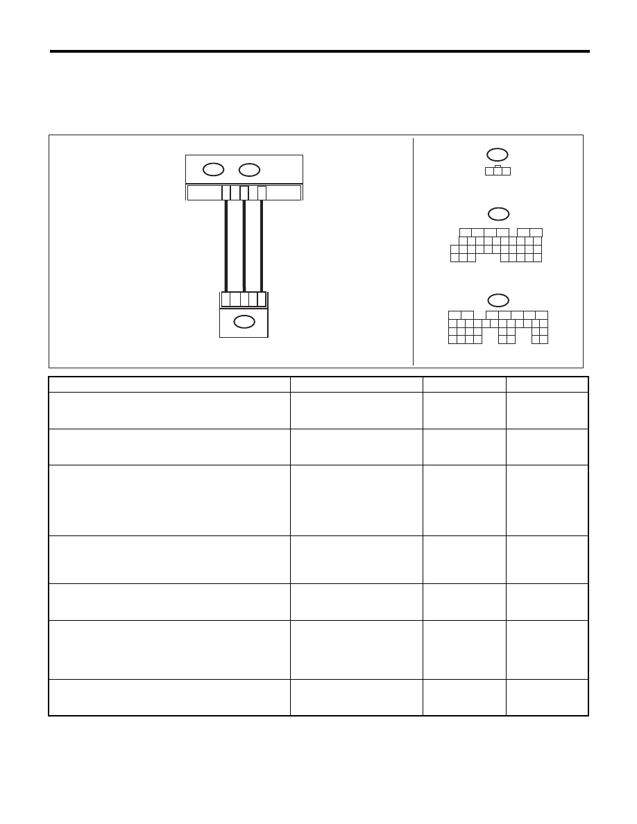
AJ:DTC P1761 LATERAL ACCELERATION SENSOR CIRCUIT LOW
DTC DETECTING CONDITION:
• Lateral G sensor open circuit or output voltage fault (Model without VDC)
• CAN communication malfunction (Model with VDC)
WIRING DIAGRAM:
Step
Check
Yes
No
1
CHECK VEHICLE CONDITION.
Is the vehicle a model with
VDC, which has the VDC OFF
switch on the instrument panel?
Go to step 2.
Go to step 4.
2
CHECK DTC OF TCM.
Is DTC of AT CAN communica-
tion detected?
Perform the diag-
nosis according to
DTC.
Go to step 3.
3
CHECK DTC OF ABS.
Is DTC of ABS detected?
Perform the diag-
nosis according to
DTC of ABS.
Temporary poor
contact occurs.
Recheck for defec-
tive parts in har-
ness and
connectors.
4
CHECK OUTPUT OF LATERAL G SENSOR
USING SUBARU SELECT MONITOR.
Read the value of “Lateral G Sensor” using
Subaru Select Monitor.
Is the reading indicated on
monitor display 2.3 to 2.7 V
when lateral G sensor is level?
Go to step 5.
Go to step 8.
5
CHECK POOR CONTACT IN CONNECTOR.
Turn the ignition switch to OFF.
Is there poor contact in connec-
tor between TCM and lateral G
sensor?
Repair the connec-
tor.
Go to step 6.
6
CHECK ABSCM&H/U.
1) Connect all connectors.
2) Perform the Clear Memory Mode.
3) Perform the Inspection Mode.
4) Read the DTC.
Is the same DTC displayed?
Replace the TCM.
<Ref. to 5AT-60,
Transmission Con-
trol Module
(TCM).>
Go to step 7.
7
CHECK OTHER DTC DETECTION.
Is any other DTC displayed?
Perform the diag-
nosis according to
DTC.
Temporary poor
contact occurs.
AT-04479
2
1
3
B359
B7
B9
B55
B:
TCM
B359
1 2 3
B:
B55
5
6
7
2
1
3
4
29
10 11 12 13 14 15
25
24
16
30
9
8
17 18 19
20
28
21 22 23
32
31
26 27
33
34 35
A:
B54
16
10 11 12 13 14 15
25
24
30
9
8
7
17 18 19 20
28
21 22 23
29
32
31
1
2
3
4
5
6
27
26
33 34 35
LATERAL G SENSOR
A:
B54
A18
Нет комментариевНе стесняйтесь поделиться с нами вашим ценным мнением.
Текст