Subaru Legacy IV (2008 year). Service manual — part 965
PS-22
Steering Gearbox
POWER ASSISTED SYSTEM (POWER STEERING)
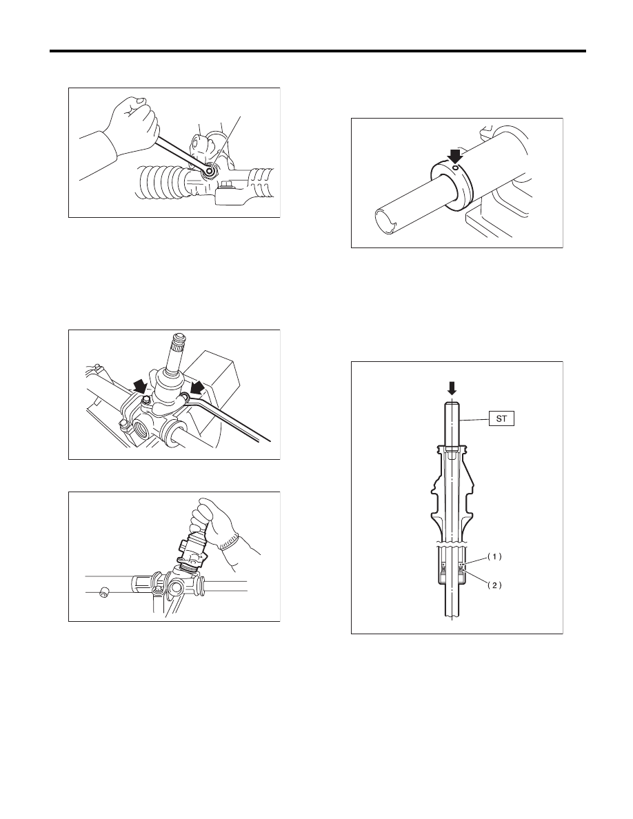
7) Tighten the adjusting screw until it can no longer
be tightened.
8) Remove the tie-rod using ST.
ST
926230000
SPANNER
9) Loosen the adjusting screw, and remove the
spring and sleeve.
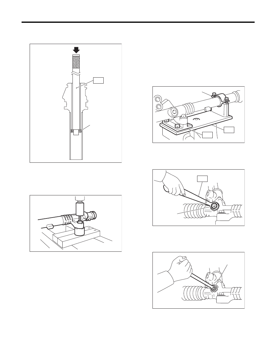
10) Remove the two bolts securing valve assem-
bly.
11) Carefully draw out the input shaft and remove
the valve assembly.
12) Using a drill, release the crimping of holder.
CAUTION:
Make a hole of 2 mm (0.08 in) depth using a drill
with 3 mm (0.12 in) diameter.
13) Remove the holder.
14) Attach the ST to the pinion housing side of the
rack, and push out the rack together with the outer
side oil seal.
ST
34199FE000
INSTALLER & REMOVER
NOTE:
Block the pipe connection of steering body to pre-
vent fluid from flowing out.
(1) Adjusting screw
PS-00495
(1)
PS-00116
PS-00117
(1) Rack piston
(2) Outer side oil seal
PS-00516
PS-00064
PS-23
Steering Gearbox
POWER ASSISTED SYSTEM (POWER STEERING)
15) Insert the ST from pinion housing side and re-
move the oil seal using a press.
ST
34099FA140
OIL SEAL REMOVER
16) Using a press, remove the bushing of gearbox
installation portion.
2. CONTROL VALVE
1) Disconnect the pipes A and B from gearbox.
2) Secure the gearbox removed from vehicle in a
vise using ST.
ST1
926200000
STAND
ST2
34199AG000 BOSS D
CAUTION:
Secure the gearbox in a vise using ST as shown
in the figure. Do not secure the gearbox without
this ST.
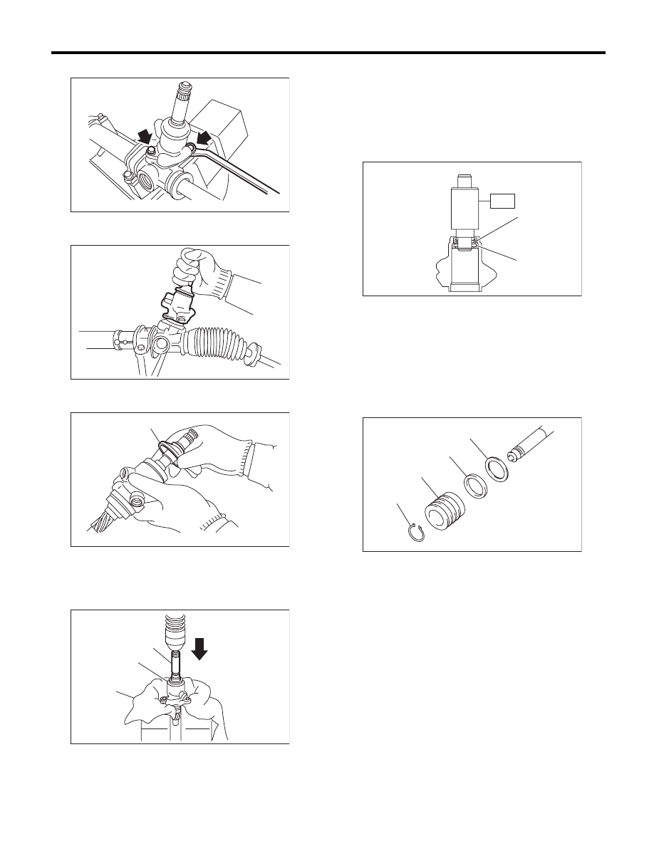
3) Using the ST, loosen the lock nut.
ST
926230000
SPANNER
4) Tighten the adjusting screw until it can no longer
be tightened.
5) Loosen the adjusting screw, and remove the
spring and sleeve.
(1) Press
(2) Oil seal
PS-00138
(2)
(1)
ST
PS-00517
(1) Clamp
(1) Lock nut
(1) Adjusting screw
PS-00492
(1)
ST1
ST2
PS-00494
ST
(1)
PS-00495
(1)
PS-24
Steering Gearbox
POWER ASSISTED SYSTEM (POWER STEERING)
6) Remove the two bolts securing valve assembly.
7) Carefully draw out the input shaft and remove
the valve assembly.
8) Put a vinyl tape around the spline portion, and
slide the dust cover to remove.
9) Using a press, remove the pinion & valve as-
sembly from valve housing.
10) Using the ST and a press, remove the bushing
and oil seal from the valve housing.
ST
34199AG090 INSTALLER & REMOVER
CAUTION:
• Do not apply a force to the end surface of
valve housing.
• Do not reuse the oil seal after removal.
11) Using a snap ring pliers, remove the snap ring,
valve, oil seal and back-up washer.
CAUTION:
Be careful not to scratch the pinion and valve
assembly.
(1) Dust cover
(1) Pinion & valve ASSY
(2) Valve housing
(3) Cloth
PS-00116
PS-00143
PS-00144
(1)
(2)
(3)
(1)
PS-00149
(1) Oil seal
(2) Bushing
(1) Snap ring
(2) Valve
(3) Oil seal
(4) Back-up ring
(2)
(1)
ST
PS-00855
PS-00518
(1)
(2)
(3)
(4)
PS-25
Steering Gearbox
POWER ASSISTED SYSTEM (POWER STEERING)
D: ASSEMBLY
1. RACK HOUSING ASSEMBLY
1) Using a press, install the bushing to gearbox in-
stallation portion.
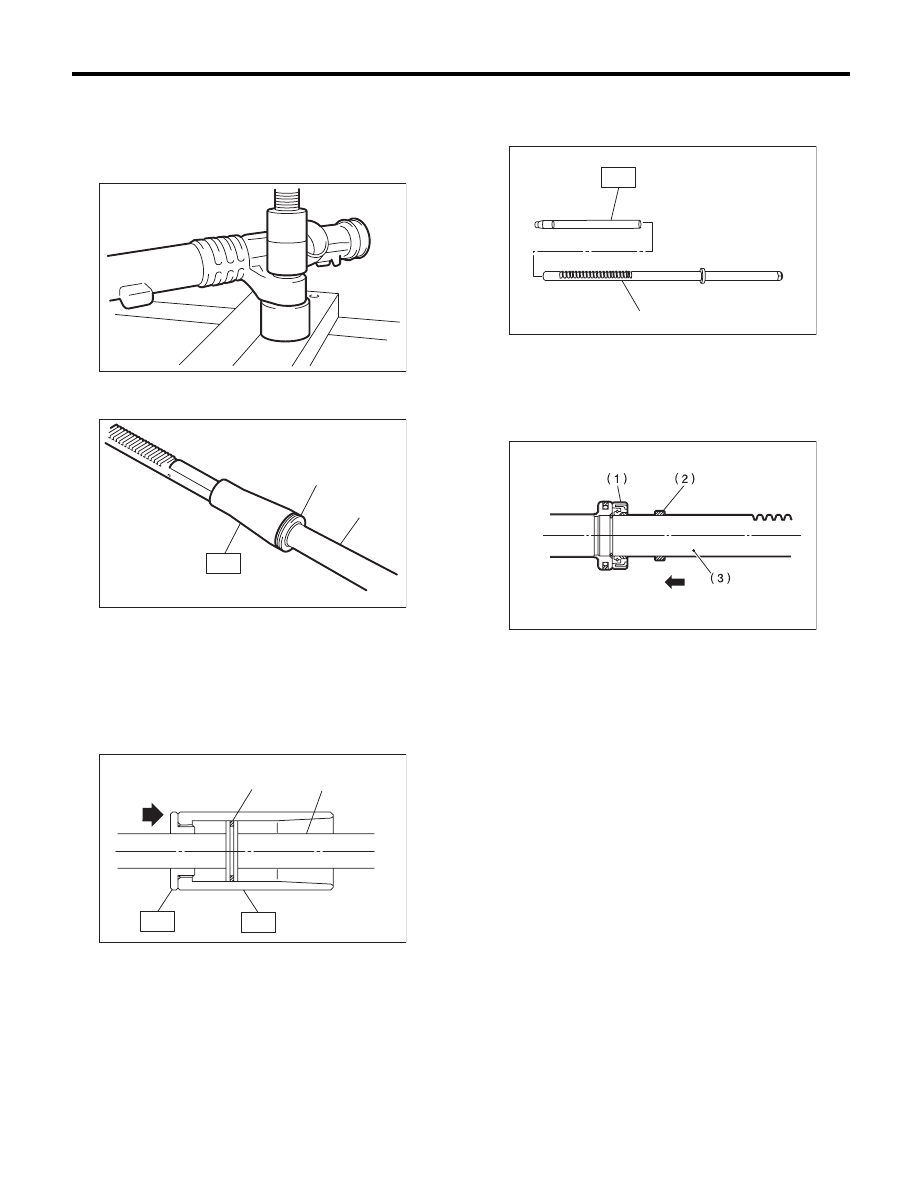
2) Insert the ST to rack.
ST
34199AG030 GUIDE
3) Install the seal ring to piston portion of rack.
4) Using the ST, form the seal ring properly.
ST1
34199AG080 FORMER PISTON
ST2
34199AG050 GUIDE G (24)
5) Attach the ST to the teeth of rack assembly, and
insert the oil seal into the rack.
ST
926390001
COVER & REMOVER
6) Remove the ST from the rack assembly.
7) Install the back-up washer from the gear side of
rack.
8) Check the threaded end of holder and gearbox
cylinder end for burrs, damage, etc. Correct if
faulty.
9) Apply a coat of grease to the grooves in rack,
sliding surface of sleeve and sealing surface of pis-
ton. Then insert the rack into steering body from
cylinder side.
10) Temporarily tighten a new holder to the gear-
box cylinder.
(1) Seal ring
(2) Rack
(1) Seal ring
(2) Rack
PS-00519
PS-00520
ST
(1)
(2)
PS-00559
(2)
(1)
ST1
ST2
(1) Rack ASSY
(1) Oil seal
(2) Back-up washer
(3) Rack
(1)
PS-00161
ST
PS-00077
Нет комментариевНе стесняйтесь поделиться с нами вашим ценным мнением.
Текст