Subaru Legacy IV (2008 year). Service manual — part 168

EN(H4SO)(diag)-275
Diagnostic Procedure with Diagnostic Trouble Code (DTC)
ENGINE (DIAGNOSTICS)
16
CHECK REAR OXYGEN SENSOR CONNEC-
TOR AND COUPLING CONNECTOR.
Has water entered the connec-
tor?
Completely
remove any water
inside.
Go to step 18.
17
CHECK FRONT OXYGEN (A/F) SENSOR
AND REAR OXYGEN SENSOR DATA.
1) Warm up the engine until engine coolant
temperature is higher than 75°C (167°F), then
keep the engine idling for 5 minutes or more.
2) Read the data of rear oxygen sensor signal
using Subaru Select Monitor or general scan
tool.
NOTE:
• SUBARU SELECT MONITOR
For detailed operation procedure, refer to
“READ CURRENT DATA FOR ENGINE”. <Ref.
to EN(H4SO)(diag)-33, Subaru Select Moni-
tor.>
• General Scan Tool
For detailed operation procedures, refer to the
general scan tool operation manual.
Is a voltage of 0.8 V or more
maintained for 5 minutes or
more?
Replace the front
oxygen (A/F) sen-
sor. <Ref. to
FU(H4SO)-35,
Front Oxygen (A/F)
Sensor.>
Go to step 18.
18
CHECK HARNESS BETWEEN ECM AND
REAR OXYGEN SENSOR CONNECTOR.
1) Turn the ignition switch to OFF.
2) Disconnect the connectors from ECM and
rear oxygen sensor.
3) Measure the resistance of harness between
ECM and rear oxygen sensor connector.
Connector & terminal
(B135) No. 4 — (E23) No. 3:
(B134) No. 29 — (E23) No. 4:
Is the resistance less than 1
:? Go to step 19.
Repair the harness
and connector.
NOTE:
In this case, repair
the following item:
• Open circuit in
harness between
ECM and rear oxy-
gen sensor con-
nector
• Poor contact of
coupling connector
19
CHECK HARNESS BETWEEN ECM AND
REAR OXYGEN SENSOR CONNECTOR.
1) Connect the connector to ECM.
2) Turn the ignition switch to ON.
3) Measure the voltage between rear oxygen
sensor connector and chassis ground.
Connector & terminal
(E23) No. 3 (+) — Chassis ground (–):
Is the voltage 0.2 — 0.5 V?
Replace the rear
oxygen sensor.
<Ref. to
FU(H4SO)-37,
Rear Oxygen Sen-
sor.>
Repair the harness
and connector.
NOTE:
In this case, repair
the following item:
• Open circuit of
harness between
the ECM and rear
oxygen sensor
• Poor contact in
ECM connector
• Poor contact of
coupling connector
Step
Check
Yes
No
EN(H4SO)(diag)-276
Diagnostic Procedure with Diagnostic Trouble Code (DTC)
ENGINE (DIAGNOSTICS)
DA:DTC P2101 THROTTLE ACTUATOR CONTROL MOTOR CIRCUIT RANGE/
PERFORMANCE
DTC DETECTING CONDITION:
• Immediately at fault recognition
• GENERAL DESCRIPTION <Ref. to GD(H4SO)-182, DTC P2101 THROTTLE ACTUATOR CONTROL
MOTOR CIRCUIT RANGE/PERFORMANCE, Diagnostic Trouble Code (DTC) Detecting Criteria.>
TROUBLE SYMPTOM:
• Improper idling
• Poor driving performance
• Engine stalls.
CAUTION:
After repair or replacement of faulty parts, perform Clear Memory Mode <Ref. to EN(H4SO)(diag)-50,
OPERATION, Clear Memory Mode.>, and Inspection Mode <Ref. to EN(H4SO)(diag)-41, PROCEDURE,
Inspection Mode.>.
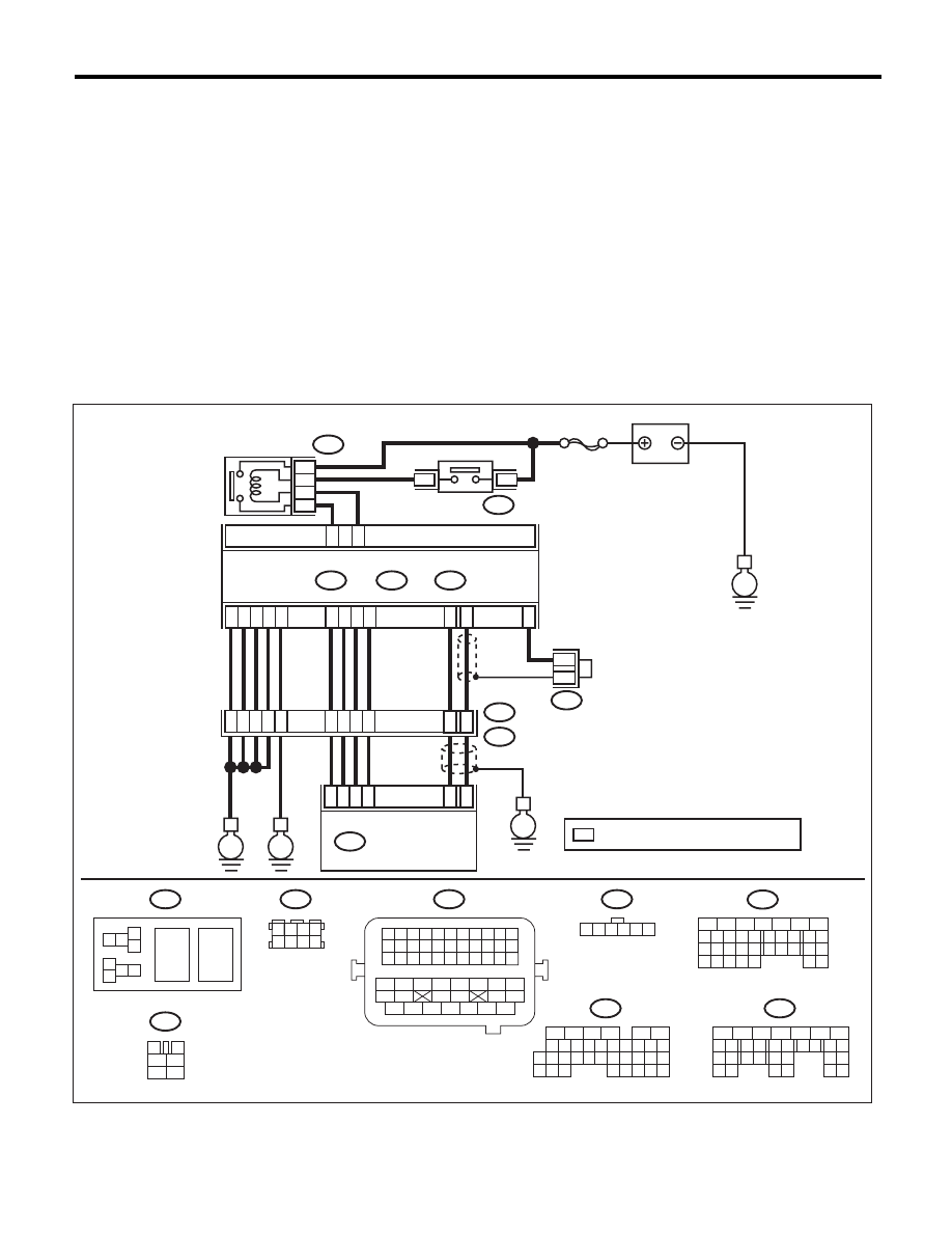
WIRING DIAGRAM:
EN-06838
SBF-7
B134
A:
B137
B136
D:
B362
C:
E
C1
C21
D4
D5
A29
A19
D3
D7
D1
D2
A5
A28
A18
C6
ECM
5
8
7
6
B362
B47
B21
E57
B122
1 2
7 8
3
4
5
6
1 2 3 4 5 6 7 8 9 10 11
12 13 14 15 16 17 18 19 20 21 22
23 24 25
34 35
36 37 38 39 40 41
48 49
50 51 52 53 54
42 43
44 45
46 47
26 27 28 29 30 31 32 33
1 2 3 4
5 6 7 8
1
2
7
8 9
5
6
3
4
10 11 12
19 20 21
29
30 31
13 14 15 16 17
27
28
18
22 23
24 25
26
1
2
8 9
5
6
3
4
10 11 12
19 20 21
29 30
31
13 14 15 16
17
27
28
18
22 23 24 25 26
7
32 33 34 35
B134
A:
B136
C:
B137
D:
BATTERY
ELECTRONIC
THROTTLE
CONTROL RELAY
MAIN RELAY
1 2 3 4 5 6
E2
B21
B122
E
E
E
39
20
E57
4
6
1
2
3
5
34
35
36
37
52
*
*
ELECTRONIC
THROTTLE CONTROL
: TERMINAL No. OPTIONAL ARRANGEMENT
*
18
17
38
19
8
5
6
10 11 12 13 14 15
7
2
1
3
4
16
30
19 20
22
28 29
9
17
18
25
21
23 24
32
31
26 27
33 34
3
4
1
2
5
6
6
4
B47

EN(H4SO)(diag)-277
Diagnostic Procedure with Diagnostic Trouble Code (DTC)
ENGINE (DIAGNOSTICS)
Step
Check
Yes
No
1
CHECK ELECTRONIC THROTTLE CON-
TROL RELAY.
1) Turn the ignition switch to OFF.
2) Remove the electronic throttle control relay.
3) Connect the battery to terminals No. 5 and
No. 6 of electronic throttle control relay.
4) Measure the resistance between electronic
throttle control relay terminals.
Terminals
No. 8 — No. 7:
Is the resistance less than 1
:? Go to step 2.
Replace the elec-
tronic throttle con-
trol relay. <Ref. to
FU(H4SO)-42,
Electronic Throttle
Control Relay.>
2
CHECK POWER SUPPLY OF ELECTRONIC
THROTTLE CONTROL RELAY.
Measure the voltage between electronic throttle
control relay connector and chassis ground.
Connector & terminal
(B362) No. 8 (+) — Chassis ground (–):
Is the voltage 10 V or more?
Go to step 3.
Repair the open or
ground short circuit
of power supply
circuit.
3
CHECK HARNESS BETWEEN ECM AND
ELECTRONIC THROTTLE CONTROL RE-
LAY.
1) Disconnect the connectors from ECM.
2) Turn the ignition switch to ON.
3) Measure the voltage between electronic
throttle control relay connector and chassis
ground.
Connector & terminal
(B362) No. 6 (+) — Chassis ground (–):
Is the voltage 10 V or more?
Repair the short
circuit to power in
harness between
ECM and elec-
tronic throttle con-
trol relay.
Go to step 4.
4
CHECK HARNESS BETWEEN ECM AND
ELECTRONIC THROTTLE CONTROL RE-
LAY.
1) Turn the ignition switch to OFF.
2) Measure the resistance between electronic
throttle control relay connector and chassis
ground.
Connector & terminal
(B362) No. 6 — Chassis ground:
(B362) No. 7 — Chassis ground:
Is the resistance 1 M
: or
more?
Go to step 5.
Repair the short
circuit in harness
to ground between
ECM and elec-
tronic throttle con-
trol relay
connector.
5
CHECK HARNESS BETWEEN ECM AND
ELECTRONIC THROTTLE CONTROL RE-
LAY.
Measure the resistance between ECM and
electronic throttle control relay connector.
Connector & terminal
(B136) No. 21 — (B362) No. 6:
(B136) No. 1 — (B362) No. 7:
Is the resistance less than 1
:? Go to step 6.
Repair the open
circuit in harness
between ECM and
electronic throttle
control relay con-
nector.
6
CHECK HARNESS BETWEEN ECM AND
ELECTRONIC THROTTLE CONTROL.
1) Turn the ignition switch to OFF.
2) Disconnect the connectors from electronic
throttle control.
3) Measure the resistance between ECM and
chassis ground.
Connector & terminal
(B134) No. 19 — Chassis ground:
(B134) No. 18 — Chassis ground:
(B134) No. 18 — (B136) No. 6:
(B134) No. 28 — Chassis ground:
Is the resistance 1 M
: or
more?
Go to step 7.
Repair the short
circuit to ground in
harness between
ECM and elec-
tronic throttle con-
trol connector.

EN(H4SO)(diag)-278
Diagnostic Procedure with Diagnostic Trouble Code (DTC)
ENGINE (DIAGNOSTICS)
7
CHECK SHORT CIRCUIT INSIDE THE ECM.
1) Connect the connector to ECM.
2) Measure the resistance between electronic
throttle control connector and engine ground.
Connector & terminal
(E57) No. 6 — Engine ground:
(E57) No. 4 — Engine ground:
Is the resistance 1 M
: or
more?
Go to step 8.
Repair the short
circuit to ground in
harness between
ECM and elec-
tronic throttle con-
trol connector.
Replace the ECM if
defective. <Ref. to
FU(H4SO)-39,
Engine Control
Module (ECM).>
8
CHECK HARNESS BETWEEN ECM AND
ELECTRONIC THROTTLE CONTROL.
1) Disconnect the connectors from ECM.
2) Measure the resistance of harness between
ECM and electronic throttle control connector.
Connector & terminal
(B134) No. 18 — (E57) No. 6:
(B134) No. 28 — (E57) No. 4:
(B134) No. 29 — (E57) No. 3:
Is the resistance less than 1
:? Go to step 9.
Repair the harness
and connector.
NOTE:
In this case, repair
the following item:
• Open circuit in
harness between
ECM and electron-
ic throttle control
connector
• Poor contact of
coupling connector
9
CHECK HARNESS BETWEEN ECM AND
ELECTRONIC THROTTLE CONTROL.
1) Connect the connector to ECM.
2) Measure the resistance between electronic
throttle control connector and engine ground.
Connector & terminal
(E57) No. 3 — Engine ground:
Is the resistance less than 5
:? Go to step 10.
Repair the harness
and connector.
NOTE:
In this case, repair
the following item:
• Open circuit of
harness between
ECM and engine
ground
• Poor contact in
ECM connector
• Poor contact of
coupling connector
10
CHECK HARNESS BETWEEN ECM AND
ELECTRONIC THROTTLE CONTROL.
1) Turn the ignition switch to ON.
2) Measure the voltage between electronic
throttle control connector and engine ground.
Connector & terminal
(E57) No. 6 (+) — Engine ground (–):
(E57) No. 4 (+) — Engine ground (–):
Is the voltage 4.85 V or more?
Repair the short
circuit to power in
the harness
between ECM and
electronic throttle
control connector.
Go to step 11.
11
CHECK HARNESS BETWEEN ECM AND
ELECTRONIC THROTTLE CONTROL.
1) Turn the ignition switch to OFF.
2) Disconnect the connectors from ECM.
3) Measure the resistance between ECM con-
nectors.
Connector & terminal
(B134) No. 19 — (B134) No. 18:
(B134) No. 19 — (B134) No. 28:
Is the resistance 1 M
: or
more?
Go to step 12.
Repair the short
circuit to power in
the harness
between ECM and
electronic throttle
control connector.
Step
Check
Yes
No
Нет комментариевНе стесняйтесь поделиться с нами вашим ценным мнением.
Текст