Subaru Legacy IV (2008 year). Service manual — part 1169

LAN(diag)-10
Control Module I/O Signal
LAN SYSTEM (DIAGNOSTICS)
Manual switch (UNLOCK)
i84
29
Less than 1
:
Door unlock switch ON
Door lock power supply
i84
34
10 — 13 V
Always
All door lock output
i84
7
10 — 13 V
Manual lock switch, door key switch ON
Driver’s door UNLOCK
output
i84
23
10 — 13 V
Driver’s seat unlock signal ON
All door UNLOCK output
i84
8
10 — 13 V
ALL door unlock signals ON
Rear gate UNLOCK output
i84
22
10 — 13 V
When the rear gate release switch ON
with all seats unlocked
Key/shift lock power supply
B281
1
10 — 13 V
Always
Shift lock output
B280
6
10 — 13 V
Ignition switch ON, shift position “P”
range, foot brake ON (Only AT)
Key locking output
B280
5
10 — 13 V
Except P range, ignition key is inserted,
ignition switch ON (AT model)
Wiper deicer switch
i84
14
Less than 1
:
Wiper deicer switch ON
Wiper deicer relay output
B280
14
1 V or less
Wiper deicer relay ON
Rear defogger switch
i84
28
Less than 1
:
Rear defogger switch ON
Rear defogger relay output
B280
16
1 V or less
Rear defogger relay ON
Shift switch (ON)
B281
26
Less than 1
:
At Manual mode
Shift switch (UP)
B281
15
Less than 1
:
At Manual mode UP
Shift switch (DOWN)
B281
25
Less than 1
:
At Manual mode DOWN
P range switch
B281
13
Less than 1
:
Shift range P position
Impact sensor
B281
5
8 V or more
(pulse signal is usually used)
Impact sensor ON
(Model with impact sensor)
Fuel level sensor
B281
19
0 — 102.3
:
Resistance differs according to the fuel
level (displays resistance combining
level gauge main and sub)
Ambient sensor
B281
3
0.5 — 4.5 V
SIG
B281
10
0 V
GND
Seat belt switch
(driver’s seat)
i84
4
Less than 1
:
When driver’s seat belt is not worn
Seat belt switch
(Passenger’s seat)
i84
13
Less than 1
:
When passenger’s seat belt is not worn
Seat belt warning light
(driver’s seat)
i84
20
Less than 1
:
When driver’s seat belt is worn
Seat belt warning light
(Passenger’s seat)
B281
27
Less than 1
:
When passenger’s seat belt is worn
Rear wiper switch (ON)
B281
6
Less than 1
:
Rear wiper switch ON
Rear wiper switch (INT)
B281
18
Less than 1
:
Rear wiper switch ON
Rear washer switch
B281
27
Less than 1
:
Rear washer switch ON
Rear wiper power supply
B280
21
10 — 13 V
Ignition switch ON
Rear wiper ON output
B280
1
10 — 13 V
Rear wiper switch ON
Rear wiper return
B280
8
10 — 13 V
At wiper reversing
1 — 8
10 — 13 V
Room light output
B280
3
1 V or less
When LOCK, UNLOCK
with keyless entry
Key ring illumination output
B280
4
1 V or less
Ignition key removed,
driver’s door open
Turn hazard output
B280
12
1 V or less
When operating keyless entry
answer back
Keyless Buzzer Output
i84
6
10 — 13 V
When operating keyless entry
answer back
Description
Connector
No.
Terminal
No.
Signal (V)
Note
Ignition switch ON
(engine OFF)

LAN(diag)-11
Control Module I/O Signal
LAN SYSTEM (DIAGNOSTICS)
B: WIRING DIAGRAM
<Ref. to WI-200, WIRING DIAGRAM, CAN Communication System.> <Ref. to WI-114, AUTO A/C MODEL,
WIRING DIAGRAM, Air Conditioning System.>
Security horn output
B280
11
1 V or less
When operating security horn
Security indicator light
output
i84
33
Approx. 1 V
At ignition key removed,
immobilizer operating
TPMS registration check
signal input
B281
4
1 V or less
When inputting registration
check signal
Keyless communication
i84
9
Serial communication
At keyless entry signal received
High speed CAN circuit
B280
20
Between B20 — B30
Serial communication
At communicating
(sending and receiving)
High speed CAN circuit
B280
30
Low-speed CAN circuit 1
i84
27
Between A26 — A27
Serial communication
At communicating
(sending and receiving)
Low-speed CAN circuit 1
i84
26
Low-speed CAN circuit 2
B280
26
Between B25 — B26
Serial communication
At communicating
(sending and receiving)
(Model with auto A/C)
Low-speed CAN circuit 2
B280
25
Immobilizer antenna
B281
20 — 21
Serial communication
—
Immobilizer communica-
tion (main)
B280
18
(Back-up
28)
Serial communication
—
Subaru Select Monitor
communication
B280
19
Serial communication
—
Description
Connector
No.
Terminal
No.
Signal (V)
Note
Ignition switch ON
(engine OFF)
LAN(diag)-12
Subaru Select Monitor
LAN SYSTEM (DIAGNOSTICS)
6. Subaru Select Monitor
A: OPERATION
1. READ DIAGNOSTIC TROUBLE CODE
(DTC)
NOTE:
• DTC is displayed in the sequence of inputting.
(When entering two DTCs or more simultaneously,
they are displayed in the sequence of priority.)
• When more than one DTC is displayed, perform
the diagnosis of top one.
1) Prepare the Subaru Select Monitor kit.
2) Connect the diagnosis cable to Subaru Select
Monitor.
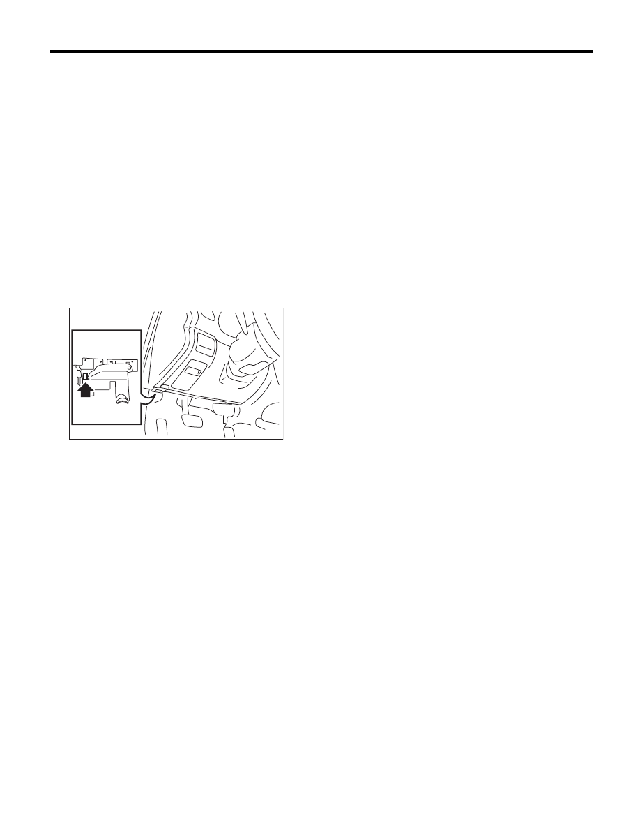
3) Connect the Subaru Select Monitor to data link
connector.
Data link connector is located in the lower portion of
instrument panel (on the driver’s side).
CAUTION:
Do not connect scan tools other than the Suba-
ru Select Monitor.
4) Turn the ignition switch to ON (engine OFF) and
run the Subaru Select Monitor.
5) On the «Main Menu» display, select the {Each
System Check}.
6) On the «System Selection Menu» display, select
the {Integ. unit mode}.
7) On the «Integ. unit mode failure diag» display,
select the {Diagnostic Code(s) Display}.
NOTE:
• For details concerning the operation procedure,
refer to the “PC application help for Subaru Select
Monitor”.
• For details concerning DTCs, refer to the List of
Diagnostic Trouble Code (DTC). <Ref. to LAN(di-
ag)-31, List of Diagnostic Trouble Code (DTC).>
2. READ CURRENT DATA
1) On the «Main Menu» display screen, select the
{Each System Check}.
2) On the «System Selection Menu» display
screen, select the {Integ. Unit mode}.
3) On the «Integ. Unit mode failure diag» display
screen, select the {Current Data Display & Save}.
4) On the «Current Data Display & Save» display
screen, select the {Data Display}.
5) Using the scroll key, scroll the display screen up
or down until the desired data is shown.
A support list contains both of analog and digital
data, and they are shown in the following table.
LAN00110

LAN(diag)-13
Subaru Select Monitor
LAN SYSTEM (DIAGNOSTICS)
3. DISPLAY OF ANALOG DATA
Items to be displayed
Unit of measure
Description
Note
BATT voltage (control)
10 — 15 V
Body integrated unit input value
Always
BATT voltage (BACKUP)
10 — 15 V
Body integrated unit input value
Always
IG power supply voltage
10 — 15 V
Body integrated unit input value
Ignition switch ON
ACC voltage
10 — 15 V
Body integrated unit input value
Ignition switch ACC
Illumination VR Voltage
0 — 5 V
Body integrated unit output
value
Illumination volume input value
Illumi. output d-ratio
0 — 100%
Body integrated unit input value
Small light ON
Illumination volume is other than bright.
Ambient temp sensor V
0 — 5 V
Body integrated unit output
value
Ignition switch ON
Ambient Temperature
–40 — 87.5°C
Body integrated unit output
value
Ignition switch ON
Fuel level voltage
0 — 8 V
Body integrated unit input value
Ignition switch ON
Fuel level resistance
0 — 102.3
:
Body integrated unit input value
Ignition switch ON
key-lock solenoid V
6 — 12 V
Body integrated unit output
value
Other than parking range
Key warning switch ON
number of regist.
0 — 4
Key No. to register
Front Wheel Speed
km/h
CAN data input value
Reception from VDC module
VDC/ABS latest f-code
DTC display
(Temporarily)
CAN data input value
It is normal when DTC is not been input
even if this code is displayed.
Reception from VDC
Blower Fan Steps
0 — 2 levels
CAN data input value
0: OFF, 1: Low, 2: 2 levels or more
Reception from air conditioner ECM
(AUTO A/C model)
Fuel level resistance 2
0 — 102.3
:
CAN data output value
Reception from body integrated unit
Fuel consumption
cc/s
CAN data input value
Reception from ECM and transmission
to center monitor
Coolant Temp.
–40 — 130°C
CAN data input value
Reception from ECM
Vehicle longitudinal G
m/s
2
CAN data input value
Reception from VDC unit
SPORT Shift Stages
0 — 7 levels
CAN data input value
(0: Light OFF; 1 — 5: Gear display; 6:
Fail; 7: ATF temperature High/Low)
Reception from TCM (AT model)
Shift Position
0 — 7 levels
CAN data input value
0: 1; 1: 2; 2: 3; 3: 4; 4: D; 5: N; 6: R; 7:
P shift position (8 indicates no input)
Reception from TCM (AT model)
Off delay time
OFF, Short, Normal,
Long
Body integrated unit setting
items
Customize setting
Нет комментариевНе стесняйтесь поделиться с нами вашим ценным мнением.
Текст