Subaru Legacy IV (2008 year). Service manual — part 549
EN(H6DO)(diag)-169
Diagnostic Procedure with Diagnostic Trouble Code (DTC)
ENGINE (DIAGNOSTICS)
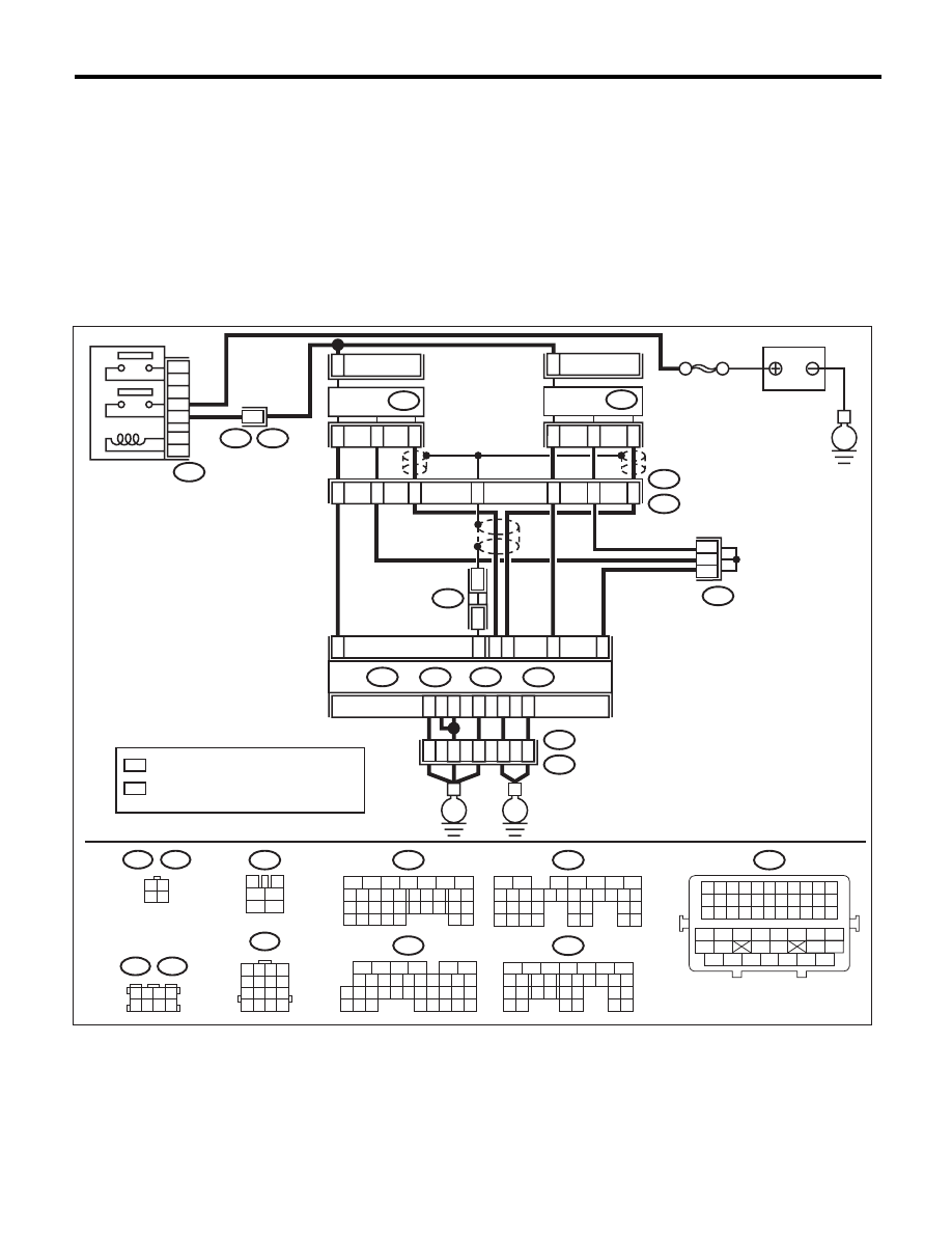
AR:DTC P0140 O2 SENSOR CIRCUIT NO ACTIVITY DETECTED
(BANK1 SENSOR2)
DTC DETECTING CONDITION:
• Two consecutive driving cycles with fault
• GENERAL DESCRIPTION <Ref. to GD(H6DO)-69, DTC P0140 O2 SENSOR CIRCUIT NO ACTIVITY
DETECTED (BANK1 SENSOR2), Diagnostic Trouble Code (DTC) Detecting Criteria.>
CAUTION:
After repair or replacement of faulty parts, perform Clear Memory Mode <Ref. to EN(H6DO)(diag)-52,
OPERATION, Clear Memory Mode.>, and Inspection Mode <Ref. to EN(H6DO)(diag)-44, PROCEDURE,
Inspection Mode.>.
WIRING DIAGRAM:
B47
3
4
5
6
1
2
B22
1 2 3 4
5 6 7 8
9 10 11 12
13 14 15 16
1 2 3 4
5 6 7 8
B83
B138
3 4
1 2
E25
E61
B47
1
2
3
5
4
6
E3
B22
14
MAIN RELAY
2
4
3
1
E25
13
15
16
E3
B22
10
11
12
9
SBF-5
BATTERY
2
E61
4
3
1
*
1
*
1
*
1
B83
B138
ECM
B134
A:
B135
B:
B136
C:
B137
D3
A3
D2
D1
D7
A5
D:
C5
*
*
2
2
C4
E
B1
B15
B4
B30
35
34
52
36
37
B21
E2
E
E
: TERMINAL No. OPTIONAL ARRANGEMENT
*
1
: TERMINAL No. OPTIONAL ARRANGEMENT
AMONG 1, 2, 5 AND 6
*
2
EN-06868
16
10 11 12 13 14 15
25
24
30
9
8
7
17 18 19 20
28
21 22 23
29
32
31
1
2
3
4
5
6
27
26
33 34 35
B136
C:
5
6
7
8
2
1
9
4
3
10
22 23
11 12 13 14 15
24 25
26
16 17
18 19 20 21
27
28 29
30 31
B137
D:
5
6
7
8
2
1
9
4
3
10
24
22 23
25
11 12 13 14 15
26 27
28
16 17 18 19
20 21
29 30 31
32 33
34 35
B135
B:
5
6
7
8
2
1
9
4
3
10
24
22 23
25
11 12 13 14 15
26 27
28
16 17
18 19 20 21
33 34
29
32
30 31
B134
A:
B21
1 2 3 4 5 6 7 8 9 10 11
12 13 14 15 16 17 18 19 20 21 22
23 24 25 26 27 28 29 30 31 32 33
34
35
42
43
36
37
38
39
48
49
50
51
52
53
54
40
41
44
45
46
47
REAR
OXYGEN
SENSOR LH
REAR
OXYGEN
SENSOR RH

EN(H6DO)(diag)-170
Diagnostic Procedure with Diagnostic Trouble Code (DTC)
ENGINE (DIAGNOSTICS)
Step
Check
Yes
No
1
CHECK REAR OXYGEN SENSOR DATA.
1) Warm up the engine until engine coolant
temperature is above 75°C (167°F), and keep
the engine speed at 3,000 rpm. (for up to 2 min-
utes)
2) Read the data of rear oxygen sensor signal
using Subaru Select Monitor or general scan
tool.
NOTE:
• SUBARU SELECT MONITOR
For detailed operation procedure, refer to
“READ CURRENT DATA FOR ENGINE”. <Ref.
to EN(H6DO)(diag)-34, Subaru Select Moni-
tor.>
• General Scan Tool
For detailed operation procedures, refer to the
general scan tool operation manual.
Is the voltage 490 mV or more? Go to step 6.
Go to step 2.
2
CHECK REAR OXYGEN SENSOR DATA.
1) Warm up the engine until engine coolant
temperature is above 75°C (167°F), and rapidly
reduce the engine speed from 3,000 rpm.
2) Read the data of rear oxygen sensor signal
using Subaru Select Monitor or general scan
tool.
NOTE:
• SUBARU SELECT MONITOR
For detailed operation procedure, refer to
“READ CURRENT DATA FOR ENGINE”. <Ref.
to EN(H6DO)(diag)-34, Subaru Select Moni-
tor.>
• General Scan Tool
For detailed operation procedures, refer to the
general scan tool operation manual.
Is the voltage 250 mV or less?
Go to step 6.
Go to step 3.
3
CHECK REAR OXYGEN SENSOR CONNEC-
TOR AND COUPLING CONNECTOR.
Has water entered the connec-
tor?
Completely
remove any water
inside.
Go to step 4.
4
CHECK HARNESS BETWEEN ECM AND
REAR OXYGEN SENSOR CONNECTOR.
1) Turn the ignition switch to OFF.
2) Disconnect the connectors from ECM and
rear oxygen sensor.
3) Measure the resistance of harness between
ECM and rear oxygen sensor connector.
Connector & terminal
(B135) No. 4 — (E61) No. 3:
(B135) No. 30 — (E61) No. 4:
Is the resistance less than 1
:? Go to step 5.
Repair the harness
and connector.
NOTE:
In this case, repair
the following item:
• Open circuit in
harness between
ECM and rear oxy-
gen sensor con-
nector
• Poor contact of
coupling connector

EN(H6DO)(diag)-171
Diagnostic Procedure with Diagnostic Trouble Code (DTC)
ENGINE (DIAGNOSTICS)
5
CHECK HARNESS BETWEEN ECM AND
REAR OXYGEN SENSOR.
1) Turn the ignition switch to OFF.
2) Disconnect the connector from rear oxygen
sensor.
3) Turn the ignition switch to ON.
4) Measure the voltage between rear oxygen
sensor connector and chassis ground.
Connector & terminal
(E61) No. 3 (+) — Chassis ground (–):
Is the voltage 0.2 — 0.5 V?
Replace the rear
oxygen sensor.
<Ref. to
FU(H6DO)-34,
Rear Oxygen Sen-
sor.>
Repair the harness
and connector.
NOTE:
In this case, repair
the following item:
• Open circuit of
harness between
the ECM and rear
oxygen sensor
• Poor contact of
the rear oxygen
sensor connector
• Poor contact in
ECM connector
6
CHECK EXHAUST SYSTEM.
Check exhaust system parts.
NOTE:
Check the following items.
• Looseness and improper attachment of ex-
haust system parts
• Damage (crack, hole etc.) of parts
• Looseness and improper attachment of parts
between front oxygen (A/F) sensor and rear ox-
ygen sensor
Is there any fault in exhaust
system?
Repair or replace
faulty parts.
Replace the rear
oxygen sensor.
<Ref. to
FU(H6DO)-34,
Rear Oxygen Sen-
sor.>
Step
Check
Yes
No
EN(H6DO)(diag)-172
Diagnostic Procedure with Diagnostic Trouble Code (DTC)
ENGINE (DIAGNOSTICS)
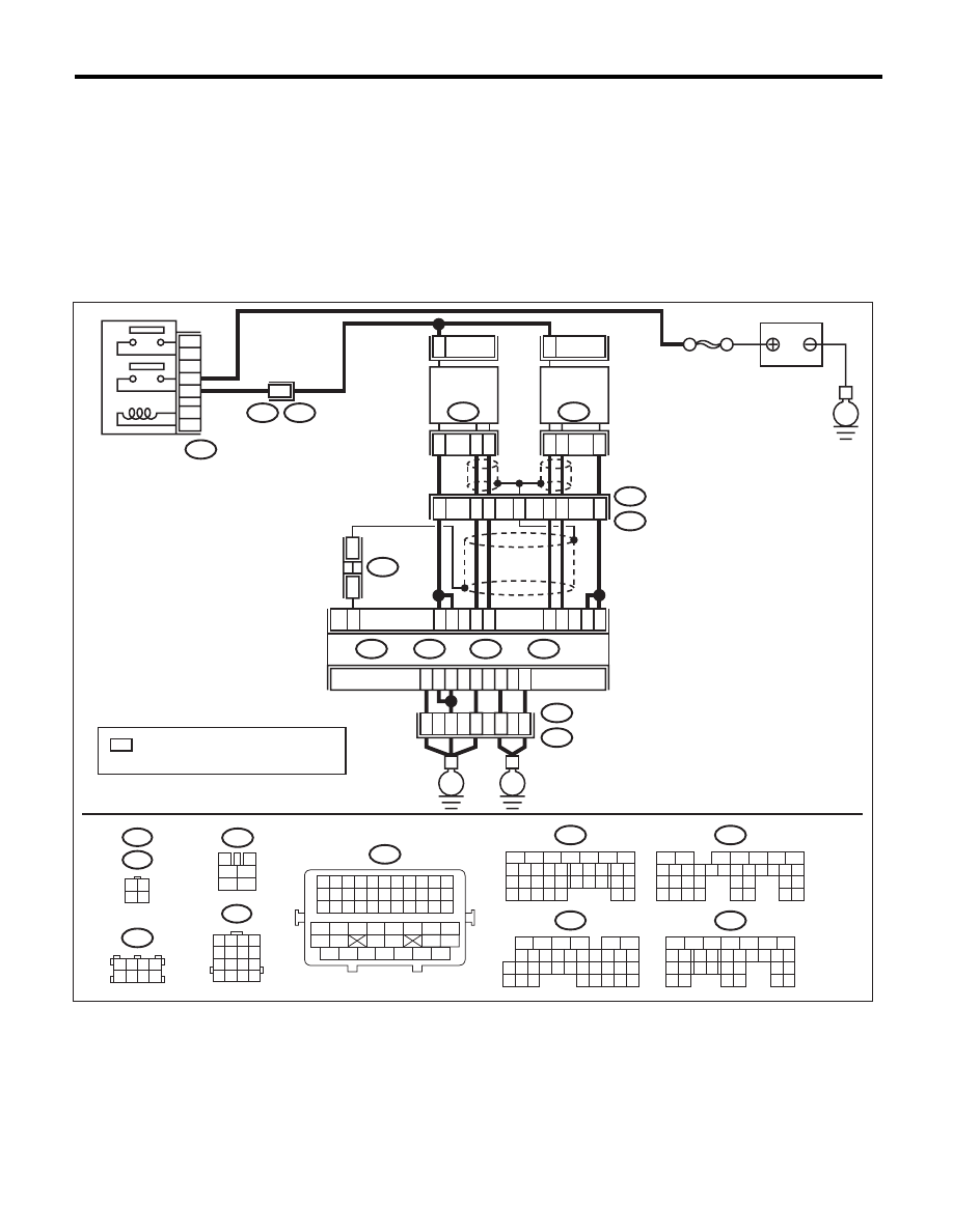
AS:DTC P0151 O2 SENSOR CIRCUIT LOW VOLTAGE (BANK 2 SENSOR 1)
DTC DETECTING CONDITION:
• Immediately at fault recognition
• GENERAL DESCRIPTION <Ref. to GD(H6DO)-71, DTC P0151 O2 SENSOR CIRCUIT LOW VOLTAGE
(BANK 2 SENSOR 1), Diagnostic Trouble Code (DTC) Detecting Criteria.>
CAUTION:
After repair or replacement of faulty parts, perform Clear Memory Mode <Ref. to EN(H6DO)(diag)-52,
OPERATION, Clear Memory Mode.>, and Inspection Mode <Ref. to EN(H6DO)(diag)-44, PROCEDURE,
Inspection Mode.>.
WIRING DIAGRAM:
SBF-5
BATTERY
E
E3
B22
B47
1
2
3
5
4
6
MAIN RELAY
E3
B22
8
: TERMINAL No. OPTIONAL ARRANGEMENT
AMONG 1, 2, 5 AND 6
*
3
4
5
6
1
2
B47
1 2 3 4
5 6 7 8
9 10 11 12
13 14 15 16
B22
3 4
1 2
E47
E24
16
10 11 12 13 14 15
25
24
30
9
8
7
17 18 19 20
28
21 22 23
29
32
31
1
2
3
4
5
6
27
26
33 34 35
B136
C:
5
6
7
8
2
1
9
4
3
10
22 23
11 12 13 14 15
24 25
26
16 17
18 19 20 21
27
28 29
30 31
B137
D:
1 2 3 4
5 6 7 8
B138
5
6
7
8
2
1
9
4
3
10
24
22 23
25
11 12 13 14 15
26 27
28
16 17 18 19
20 21
29 30 31
32 33
34 35
B135
B:
5
6
7
8
2
1
9
4
3
10
24
22 23
25
11 12 13 14 15
26 27
28
16 17
18 19 20 21
33 34
29
32
30 31
B134
A:
B11
2
E24
FRONT
OXYGEN (A/F)
SENSOR LH
3
4
B10
1
B7
B6
C2
C3
B8
4
1
3
B9
ECM
B135
B:
B134
A:
B137
D:
B136
C:
D3
A3
D2
D1
D7
A5
35
34
52
36
37
B21
E2
E
E
EN-06867
B21
1 2 3 4 5 6 7 8 9 10 11
12 13 14 15 16 17 18 19 20 21 22
23 24 25 26 27 28 29 30 31 32 33
34
35
42
43
36
37
38
39
48
49
50
51
52
53
54
40
41
44
45
46
47
2
E47
FRONT
OXYGEN (A/F)
SENSOR RH
5
6
7
4
2
1
3
B138
*
*
B1
Нет комментариевНе стесняйтесь поделиться с нами вашим ценным мнением.
Текст