Subaru Legacy IV (2008 year). Service manual — part 95
SC(H4SO)-4
General Description
STARTING/CHARGING SYSTEMS
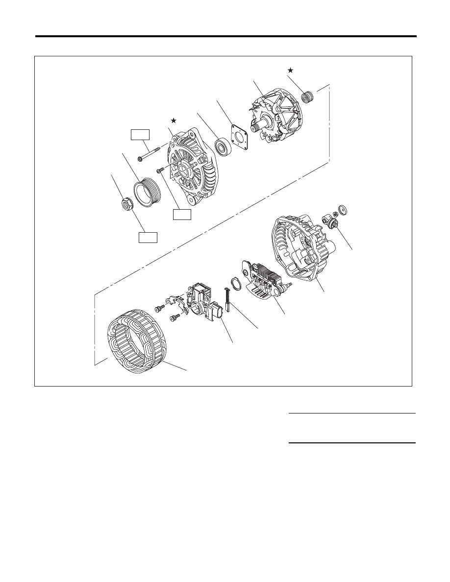
2. GENERATOR
(1)
Pulley nut
(7)
Bearing
(13)
Terminal
(2)
Pulley
(8)
Stator coil
(3)
Front cover
(9)
IC regulator with brush
Tightening torque:N·m (kgf-m, ft-lb)
(4)
Ball bearing
(10)
Brush
T1: 4.7 (0.5, 3.5)
(5)
Bearing retainer
(11)
Rectifier
T2: 108 (11.0, 79.8)
(6)
Rotor
(12)
Rear cover
(1)
(2)
(3)
(4)
(5)
(6)
(7)
(8)
(9)
(10)
(11)
(12)
(13)
T1
T1
T2
SC-02121
SC(H4SO)-5
General Description
STARTING/CHARGING SYSTEMS
C: CAUTION
• Wear appropriate work clothing, including a cap,
protective goggles and protective shoes when per-
forming any work.
• Remove contamination including dirt and corro-
sion before removal, installation or disassembly.
• Keep the disassembled parts in order and pro-
tect them from dust and dirt.
• Before removal, installation or disassembly, be
sure to clarify the failure. Avoid unnecessary re-
moval, installation, disassembly and replacement.
• Vehicle components are extremely hot after driv-
ing. Be wary of receiving burns from heated parts.
• Be sure to tighten fasteners including bolts and
nuts to the specified torque.
• Place shop jacks or rigid racks at the specified
points.
• Before disconnecting connectors of sensors or
units, be sure to disconnect the ground cable from
the battery.
SC(H4SO)-6
Starter
STARTING/CHARGING SYSTEMS
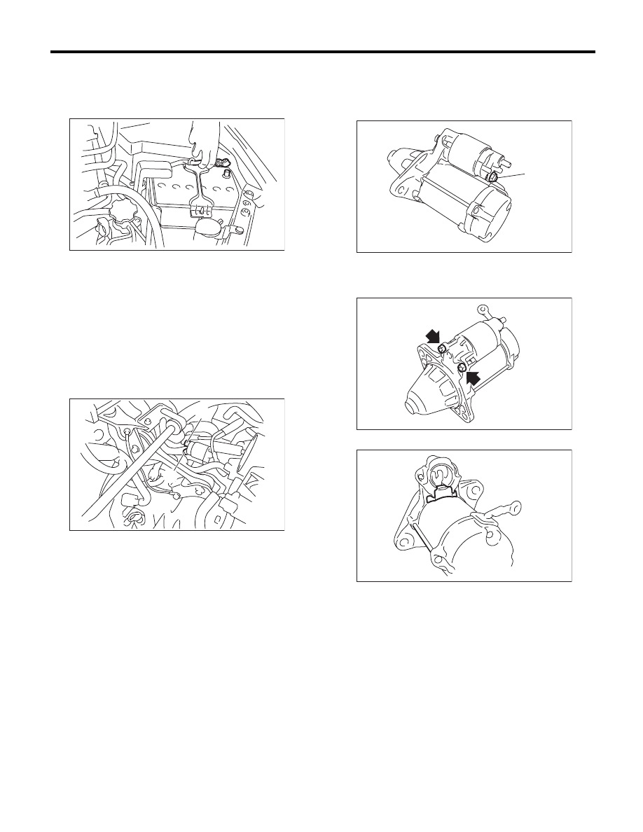
2. Starter
A: REMOVAL
1) Disconnect the ground cable from battery.
2) Remove the air intake chamber. (Non-turbo
model) <Ref. to IN(H4SO)-7, REMOVAL, Air Intake
Chamber.> <Ref. to IN(H6DO)-7, REMOVAL, Air
Intake Chamber.>
3) Remove the intercooler. (Turbo model)
<Ref. to IN(H4DOTC)-12, REMOVAL, Intercool-
er.>
4) Remove the air intake chamber stay LH. (2.5 L
non-turbo model)
5) Disconnect the connector and terminal from
starter.
6) Remove the starter from transmission.
B: INSTALLATION
Install in the reverse order of removal.
Tightening torque:
50 N·m (5.1 kgf-m, 36.9 ft-lb)
C: DISASSEMBLY
1) Loosen the nut which holds terminal M (A) of the
magnet switch assembly, then disconnect the har-
ness from the terminal.
2) Remove the nuts which secure the magnet
switch assembly and remove the magnet switch
assembly.
3) Remove the starter seal.
(A) Terminals
(B) Connector
IN-00203
SC-02038
(A)
(B)
SC-02128
(A)
SC-02129
SC-02130
SC(H4SO)-7
Starter
STARTING/CHARGING SYSTEMS
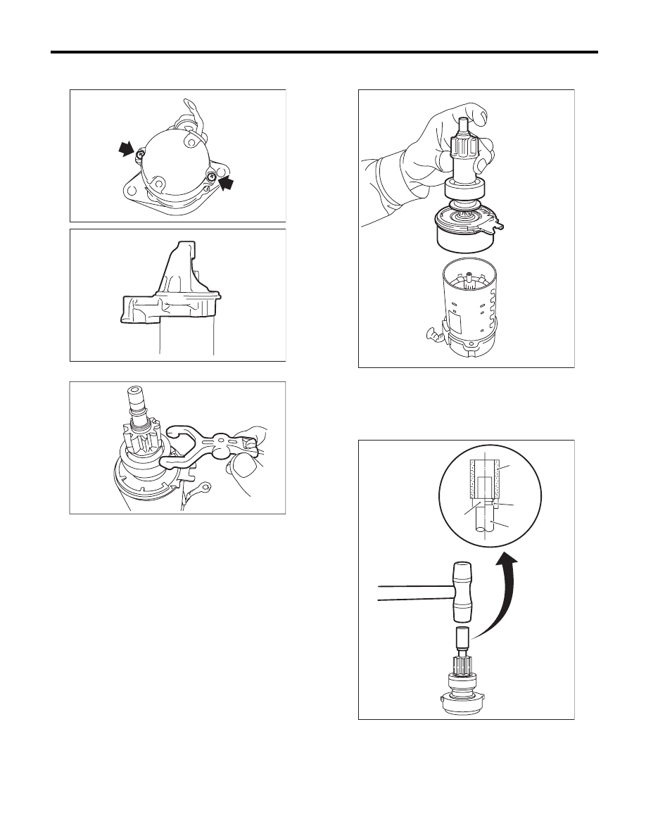
4) Remove the through bolts on both sides, and re-
move the starter housing.
5) Remove the shift lever.
6) Remove the overrunning clutch, shock absorber
bearing and shaft from the yoke as an assembly.
7) Remove the overrunning clutch from shaft as-
sembly as follows:
(1) Using a plastic hammer, remove the stopper
from snap ring by lightly tapping the stopper with
an appropriate tool (such as a fit socket wrench).
SC-02131
SC-02132
SC-02133
(A) Appropriate tool
(B) Snap ring
(C) Shaft
(D) Stopper
SC-02136
SC-02148
(A)
(B)
(C)
(D)
Нет комментариевНе стесняйтесь поделиться с нами вашим ценным мнением.
Текст