Subaru Legacy IV (2008 year). Service manual — part 703
4AT(diag)-33
Diagnostic Procedure with Diagnostic Trouble Code (DTC)
AUTOMATIC TRANSMISSION (DIAGNOSTICS)
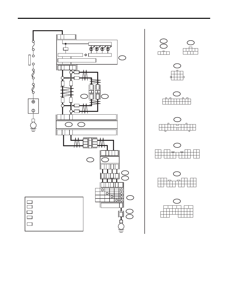
WIRING DIAGRAM:
AT-04898
MAIN SBF
SBF-6
No.
5
E
P
R
N
D
17
18
10
14
11
T7
B54
B12
T3
T3
B12
1
4
P
R
N
D
E
TCM
2
5
3
4
2
8
3
1
13
3
21
22
i10
i84
A:
B280
B:
A26
A27
B30
B20
B365
1
*
2
*
1
*
2
*
WN
WN
ON
i107
i106
*
*
*
*
ON
WN
WN
ON
ON
:
:
1
*
2
*
:
*
:
WN
:
ON
B54
B12
T7
9
8
7
6
5
4
3
2
1
10
9
12
11
8
7
6
5
4
3
2
1
5
6
7 8
2
1
9
4
3
10
24
22 23
25
11 12 13 14 15
26 27
28
16
17 18 19 20 21
33 34
29
32
30
31
35
i10
i84
B280
2
1
3 4
6 7 8 9 10
22
21
20
19
18
17
16
15
14
13
12
11
5
8
7
6
5
4
3
2
1
22 23
21
20
19
16
15
14
13
12
11
10
9
34 35
33
32
17
30
18
31
29
28
27
26
25
24
8
7
6
5
4
3
2
1
22
23
21
20
19
16
15
14
13
12
11
10
9
17
30
18
29
28
27
26
25
24
A:
B:
i107
i106
1 2 3 4 5 6 7 8 9 10
11 12 13 14 15 16 17 18 19 20
1 2 3 4
B365
WITH NAVIGATION
WITHOUT NAVIGATION
TERMINAL No. OPTIONAL ARRANGEMENT
AMONG 1, 2, 3, 11, 12 AND 13
TERMINAL No. OPTIONAL ARRANGEMENT
TERMINAL No. OPTIONAL ARRANGEMENT
AMONG 8, 9, 10, 18, 19 AND 20
CAN
JOINT
CONNECTOR
BODY INTEGRATED UNIT
COMBINATION
METER
IGNITION
SWITCH
CAN TRANSCEIVER & RECEIVER
MICRO COMPUTER
INHIBITOR
SWITCH
B
A
TTER
Y
CAN
JOINT
CONNECTOR
CAN
JOINT
CONNECTOR

4AT(diag)-34
Diagnostic Procedure with Diagnostic Trouble Code (DTC)
AUTOMATIC TRANSMISSION (DIAGNOSTICS)
Step
Check
Yes
No
1
CHECK INDICATOR LIGHT.
1) Turn the ignition switch to ON.
2) Shift the select lever to “P” range.
Does the “P” range indicator
light on combination meter illu-
minate?
Go to step 2.
Go to step 12.
2
CHECK INDICATOR LIGHT.
Does the “R” range indicator
light on combination meter illu-
minate?
Go to step 26.
Go to step 3.
3
CHECK INDICATOR LIGHT.
Does the “N” range indicator
light on combination meter illu-
minate?
Go to step 33.
Go to step 4.
4
CHECK INDICATOR LIGHT.
Does the “D” range indicator
light on combination meter illu-
minate?
Go to step 40.
Go to step 5.
5
CHECK “P” RANGE SWITCH.
Read the data of “P range” using Subaru Select
Monitor.
Is ON displayed?
Go to step 19.
Go to step 6.
6
CHECK INDICATOR LIGHT.
Shift the select lever to “R” range.
Does the “R” range indicator
light on combination meter illu-
minate?
Go to step 8.
Go to step 7.
7
CHECK “R” RANGE SWITCH.
Read the data of “R range” using Subaru Select
Monitor.
Is ON displayed?
Go to step 23.
Go to step 20.
8
CHECK INDICATOR LIGHT.
Shift the select lever to “N” range.
Does the “P” range indicator
light on combination meter illu-
minate?
Go to step 10.
Go to step 9.
9
CHECK “N” RANGE SWITCH.
Read the data of “N range” using Subaru Select
Monitor.
Is ON displayed?
Go to step 30.
Go to step 27.
10
CHECK INDICATOR LIGHT.
Shift the select lever to “D” range.
Does the “D” range indicator
light on combination meter illu-
minate?
Even if the ATF
temperature warn-
ing light blinks, the
circuit is in normal
condition at this
time. A temporary
poor contact of
connector or har-
ness may be the
cause. Repair the
harness or con-
nector in TCM and
transmission.
Go to step 11.
11
CHECK “D” RANGE SWITCH.
Read the data of “D range” using Subaru Select
Monitor.
Is ON displayed?
Go to step 37.
Go to step 34.
12
CHECK HARNESS CONNECTOR BETWEEN
INHIBITOR SWITCH AND CHASSIS
GROUND.
1) Turn the ignition switch to OFF.
2) Disconnect the connector from inhibitor
switch.
3) Measure the resistance of harness between
inhibitor switch and chassis ground.
Connector & terminal
(T7) No. 5 — Chassis ground:
Is the resistance 1
: or more? Go to step 13.
Repair the open
circuit of harness
between inhibitor
switch and chassis
ground, and poor
contact of the con-
nector.

4AT(diag)-35
Diagnostic Procedure with Diagnostic Trouble Code (DTC)
AUTOMATIC TRANSMISSION (DIAGNOSTICS)
13
CHECK HARNESS CONNECTOR BETWEEN
TCM AND INHIBITOR SWITCH.
1) Turn the ignition switch to OFF.
2) Disconnect the connector from TCM and
inhibitor switch.
3) Measure the resistance of the harness
between TCM and inhibitor switch connector.
Connector & terminal
(B54) No. 14 — (T7) No. 2:
Is the resistance less than 1
:? Go to step 14.
Repair the open
circuit of harness
between TCM and
inhibitor switch
connector, and
poor contact of the
connector.
14
CHECK INPUT SIGNAL FOR TCM.
1) Turn the ignition switch to OFF.
2) Connect the connector to TCM and inhibitor
switch.
3) Turn the ignition switch to ON.
4) Shift the select lever to “P” range.
5) Measure the voltage between TCM and
chassis ground.
Connector & terminal
(B54) No. 14 (+) — Chassis ground (–):
Is the voltage less than 1 V?
Go to step 15.
Go to step 41.
15
CHECK INPUT SIGNAL FOR TCM.
1) Shift the select lever to any range other than
“P”.
2) Measure the voltage between TCM and
chassis ground.
Connector & terminal
(B54) No. 14 (+) — Chassis ground (–):
Is the voltage 8 V or more?
Go to step 16.
Replace the TCM.
<Ref. to 4AT-61,
Transmission Con-
trol Module
(TCM).>
16
CHECK BODY INTEGRATED UNIT.
Read the data of “Inhibitor Switch” from Subaru
Select Monitor. <Ref. to LAN(diag)-12, OPERA-
TION, Subaru Select Monitor.>
Is “7” displayed?
Go to step 17.
Check the body
integrated unit.
17
CHECK BODY INTEGRATED UNIT.
Check DTC of body integrated unit.
Is DTC of CAN communication
displayed?
Perform the diag-
nosis according to
DTC.
Go to step 18.
18
CHECK COMBINATION METER.
Check the “P” range indicator light. <Ref. to IDI-
5, INSPECTION, Combination Meter System.>
Is the “P” range indicator light
bulb OK?
Go to step 41.
Replace the com-
bination meter
assembly. <Ref. to
IDI-22, Combina-
tion Meter.>
19
CHECK HARNESS CONNECTOR BETWEEN
TCM AND INHIBITOR SWITCH.
1) Turn the ignition switch to OFF.
2) Disconnect the connectors from TCM, inhib-
itor switch and combination meter.
3) Measure the resistance of harness between
TCM connector and chassis ground.
Connector & terminal
(B54) No. 14 — Chassis ground:
Is the resistance 1 M
: or
more?
Go to step 42.
Repair ground
short circuit in “P”
range circuit.
20
CHECK HARNESS CONNECTOR BETWEEN
TCM AND INHIBITOR SWITCH.
1) Turn the ignition switch to OFF.
2) Disconnect the connector from TCM and
inhibitor switch.
3) Measure the resistance of the harness
between TCM and inhibitor switch connector.
Connector & terminal
(B54) No. 13 — (T7) No. 5:
Is the resistance less than 1
:? Go to step 21.
Repair the open
circuit of harness
between TCM and
inhibitor switch
connector, and
poor contact of the
connector.
Step
Check
Yes
No

4AT(diag)-36
Diagnostic Procedure with Diagnostic Trouble Code (DTC)
AUTOMATIC TRANSMISSION (DIAGNOSTICS)
21
CHECK INPUT SIGNAL FOR TCM.
1) Turn the ignition switch to OFF.
2) Connect the connector to TCM and inhibitor
switch.
3) Turn the ignition switch to ON.
4) Shift the select lever to “R” range.
5) Measure the voltage between TCM and
chassis ground.
Connector & terminal
(B54) No. 13 (+) — Chassis ground (–):
Is the voltage less than 1 V?
Go to step 22.
Go to step 41.
22
CHECK INPUT SIGNAL FOR TCM.
1) Shift the select lever to other than “R” range.
2) Measure the voltage between TCM and
chassis ground.
Connector & terminal
(B54) No. 13 (+) — Chassis ground (–):
Is the voltage 8 V or more?
Go to step 41.
Replace the TCM.
<Ref. to 4AT-61,
Transmission Con-
trol Module
(TCM).>
23
CHECK BODY INTEGRATED UNIT.
Read the data of Shift Position from Subaru
Select Monitor. <Ref. to LAN(diag)-12, OPERA-
TION, Subaru Select Monitor.>
Is “6” displayed?
Go to step 24.
Check the body
integrated unit.
24
CHECK BODY INTEGRATED UNIT.
Check DTC of body integrated unit.
Is DTC of CAN communication
displayed?
Perform the diag-
nosis according to
DTC.
Go to step 25.
25
CHECK COMBINATION METER.
Check the “R” range indicator light. <Ref. to IDI-
5, INSPECTION, Combination Meter System.>
Is the “R” range indicator light
OK?
Go to step 41.
Replace the com-
bination meter
assembly. <Ref. to
IDI-22, Combina-
tion Meter.>
26
CHECK HARNESS CONNECTOR BETWEEN
TCM AND INHIBITOR SWITCH.
1) Turn the ignition switch to OFF.
2) Disconnect the connectors from TCM, inhib-
itor switch and combination meter.
3) Measure the resistance of harness between
TCM connector and chassis ground.
Connector & terminal
(B54) No. 13 — Chassis ground:
Is the resistance 1 M
: or
more?
Go to step 41.
Repair ground
short circuit in “R”
range circuit.
27
CHECK HARNESS CONNECTOR BETWEEN
TCM AND INHIBITOR SWITCH.
1) Turn the ignition switch to OFF.
2) Disconnect the connector from TCM and
inhibitor switch.
3) Measure the resistance of the harness
between TCM and inhibitor switch connector.
Connector & terminal
(B54) No. 11 — (T7) No. 3:
Is the resistance less than 1
:? Go to step 28.
Repair the open
circuit of harness
between TCM and
inhibitor switch
connector, and
poor contact of the
connector.
28
CHECK INPUT SIGNAL FOR TCM.
1) Turn the ignition switch to OFF.
2) Connect the connector to TCM and inhibitor
switch.
3) Turn the ignition switch to ON.
4) Shift the select lever to “N” range.
5) Measure the voltage between TCM and
chassis ground.
Connector & terminal
(B54) No. 11 (+) — Chassis ground (–):
Is the voltage less than 1 V?
Go to step 29.
Go to step 41.
Step
Check
Yes
No
Нет комментариевНе стесняйтесь поделиться с нами вашим ценным мнением.
Текст