Subaru Legacy IV (2008 year). Service manual — part 1099

SE-8
General Description
SEATS
B: CAUTION
• If the seat cushion cover is removed or replaced, make sure to perform passenger detection system ad-
justment after installing the seat to the vehicle. <Ref. to OD(diag)-15, SYSTEM CALIBRATION (REZERO-
ING), OPERATION, Subaru Select Monitor.>
If system adjustment is not performed, the occupant detection system may not function properly.
• The passenger detection system (passenger seat only) control unit and the passenger detection sensor
are fixed to the seat cushion frame. Never remove the passenger detection control unit or the pressure sen-
sor from the seat cushion frame.
• Do not replace the seat cushion pad by itself. Always replace the seat cushion pad and frame assembly
as a set. The seat cushion pad and cushion frame are adjusted as a set at the time of manufacture. If cushion
pads and cushion frames are combined from those of other vehicles or other sets, the passenger detection
system may not operate properly.
• If the seat cushion cover is removed, make sure to replace the hang wire on the seat cushion side with a
new wire.
• When removing the front seat from a side airbag loaded vehicle, follow cautions given in the airbag section.
<Ref. to AB-4, CAUTION, General Description.>
C: PREPARATION TOOL
1. GENERAL TOOL
TOOL NAME
REMARKS
Long nose plier
Used for removing the hog ring.
Hog ring pliers
Used for installing the hog ring.
TORX
®
T50
Used for removing and installing the inner seat belt assembly.
Circuit tester
Used for checking voltage and continuity.
SE-9
Front Seat
SEATS
2. Front Seat
A: REMOVAL
CAUTION:
The airbag system is fitted with a backup power
source. After disconnecting the battery ground
cable, the airbag may deploy if you do not wait
for 20 seconds before starting the service of
airbag system.
NOTE:
• When removing the front seat of memory-
equipped power seats, always perform the initialize
operation on the memory function after installing
the seat to the vehicle. <Ref. to SE-40, ADJUST-
MENT, Power Seat System.>
• Failure to do so may cause the abnormal opera-
tion of the memory function.
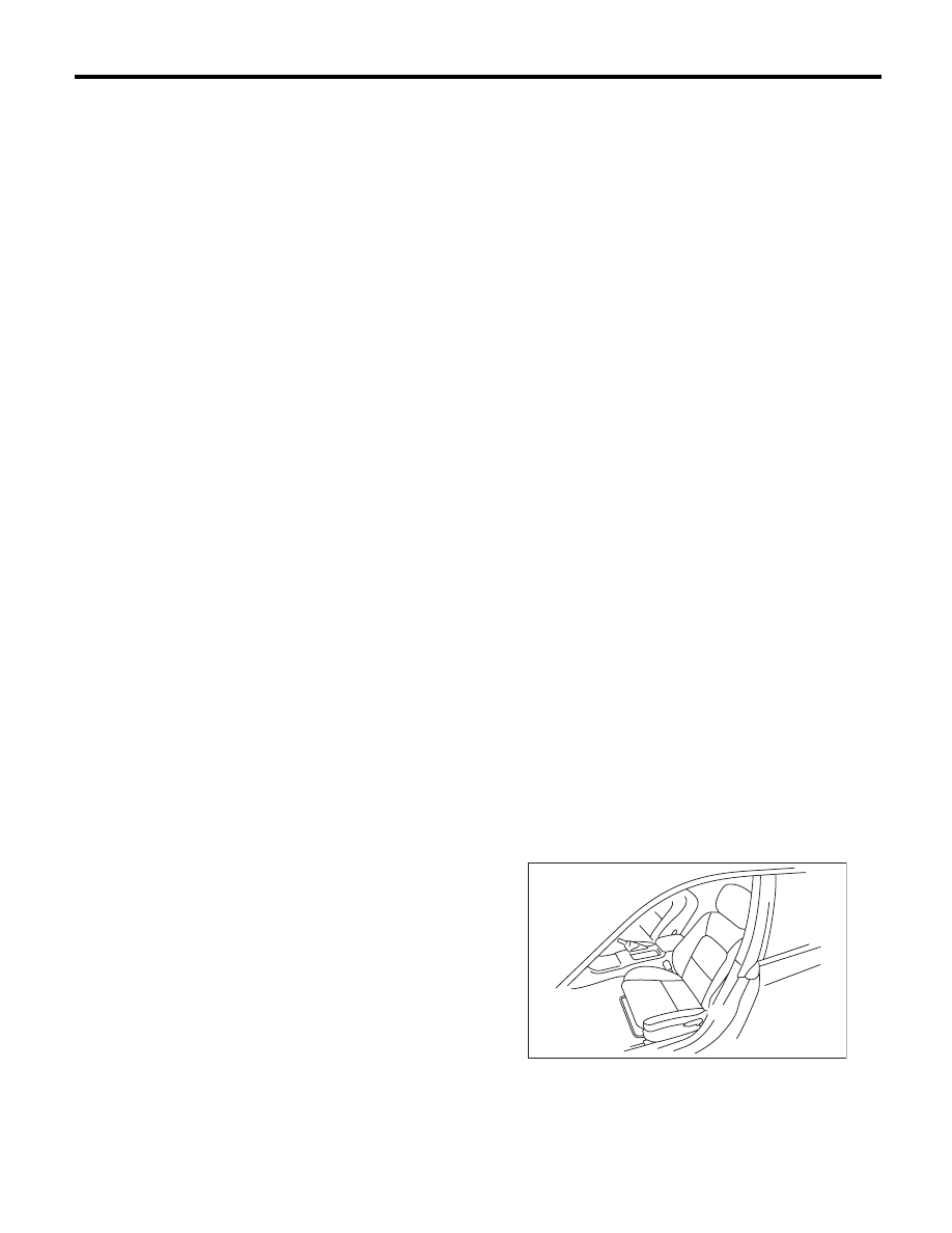
1. DRIVER’S SEAT
1) Remove the headrest.
2) Tilt the backrest forward, and move the seat for-
ward.
3) Remove the rear bolt cover, and remove the two
bolts at the rear side of the slide rail.
4) Move the seat towards the rear, and remove the
two bolts at the front side of the slide rail.
5) Disconnect the ground cable from the battery.
CAUTION:
When remove the battery negative terminal,
wait 20 seconds then go to the next procedure.
6) Disconnect the connector under the seat.
• Seat belt buckle switch connector
• Side airbag connector
• Seat heater connector (model with seat heater)
• Power seat connector (model with power seats)
7) Remove the seat from vehicle.
2. PASSENGER’S SEAT
CAUTION:
Refer to “CAUTION” of “General Description”
before starting the work. <Ref. to SE-8, CAU-
TION, General Description.>
1) Remove the headrest.
2) Tilt the backrest forward, and move the seat for-
ward.
3) Remove the rear bolt cover, and then remove
the rear side of slide rail.
4) Move the seat backward, remove the front bolt
cover, and then remove the bolt at the front side of
the slide rail.
5) Disconnect the ground cable from the battery.
CAUTION:
When remove the battery negative terminal,
wait 20 seconds then go to the next procedure.
6) Disconnect all the connectors of connector hold-
er in the backside of seat cushion.
• Harness connector of occupant detection control
module
• Side airbag connector
• Power seat connector (model with power seats)
• Seat heater connector (model with seat heater)
7) Remove the seat from vehicle.
B: INSTALLATION
CAUTION:
If a front seat is power seat with memory func-
tion, the memory function must be initialized af-
ter installing seat to the vehicle. <Ref. to SE-40,
ADJUSTMENT, Power Seat System.>
Failure to do so may cause the abnormal oper-
ation of the memory function.
Install in the reverse order of removal.
NOTE:
Tighten the slide rail installing bolt gradually in sev-
eral steps to the specified torque in the order as
shown in the figure.
Tightening torque:
Refer to “COMPONENT” of “General Descrip-
tion”. <Ref. to SE-2, COMPONENT, General
Description.>
(1)
(2)
(3)
(4)
SE-00704
SE-10
Front Seat
SEATS
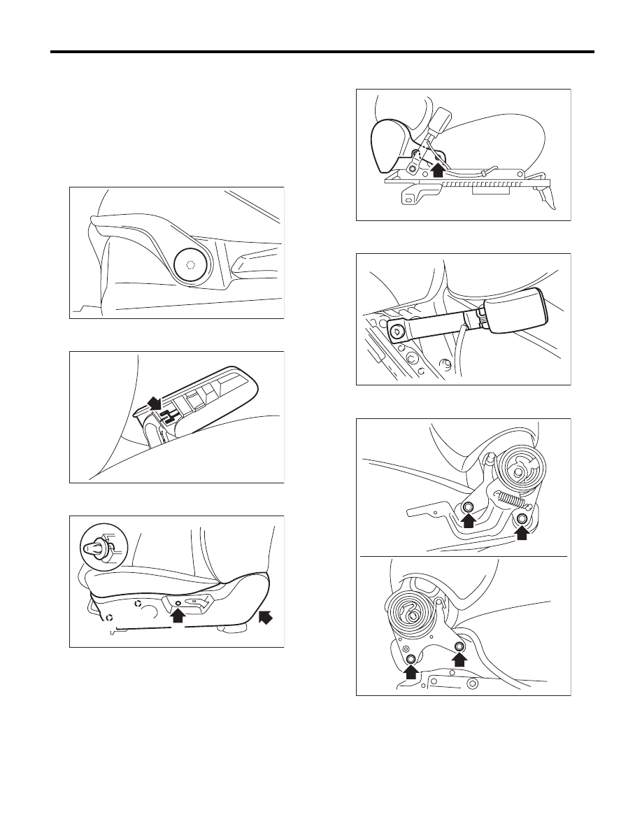
C: DISASSEMBLY
1. DRIVER’S SEAT
MANUAL SEAT
1) Remove the seat from vehicle. <Ref. to SE-9,
REMOVAL, Front Seat.>
2) Remove the seat lifter cover using a flat tip
screwdriver and loosen the inner bolt to remove the
seat lifter lever.
3) Disengage the tab while pulling the reclining le-
ver, and remove the reclining lever cover.
4) Remove screws (A) and clips (B), and then de-
tach the seat side cover outside.
5) Loosen the screws to detach the seat side cover
inside.
6) Remove the TORX
®
bolt, and then remove the
inner seat belt assembly.
7) Remove the two bolts from the reclining hinge on
each left and right side.
SE-00290
SE-00877
SE-00405
(A)
(A)
(B)
(B)
SE-00406
SE-00407
SE-00408
SE-11
Front Seat
SEATS
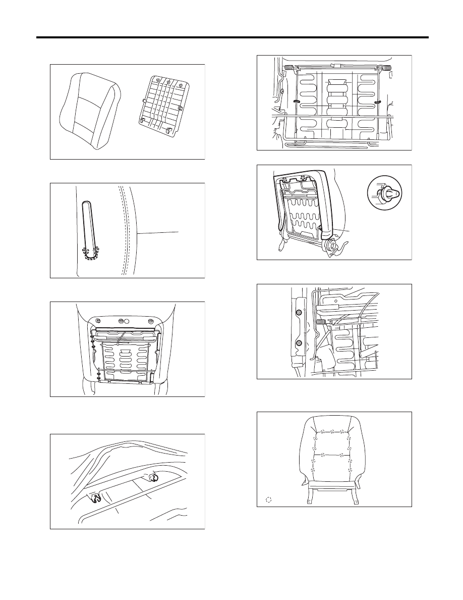
8) Remove the clips and hooks, and then detach
the backrest back cover.
9) Remove the lock clip, and then remove the lum-
ber support lever.
10) Remove the hooks and hog rings at the rear
side of backrest.
11) Remove the headrest lock bushing.
NOTE:
Push outside to remove it from the inside of seat.
12) Remove the hog rings.
13) Remove the cover frame (A).
14) Pull out the backrest frame assembly.
15) Remove the side airbag module.
16) Remove the hog rings (A) on the surface side
of backrest, and then remove the backrest cover
from backrest.
SE-00586
SE-00414
SE-00587
SE-00243
SE-00588
(A)
SE-00337
SE-00589
SE-00669
: (A)
Нет комментариевНе стесняйтесь поделиться с нами вашим ценным мнением.
Текст