Subaru Legacy IV (2008 year). Service manual — part 484
ME(H6DO)-62
Cylinder Head
MECHANICAL
(3) Turn the cylinder head upside down and
place the ST as shown in the figure.
ST
18251AA040
VALVE GUIDE ADJUSTER
(4) Before installing a new valve guide, make
sure that neither scratches nor damages exist
on the inner surface of valve guide holes in cyl-
inder head.
(5) Put a new valve guide, coated with sufficient
oil, in the cylinder head, and insert the ST1 into
valve guide. Press in until the valve guide upper
end is flush with the upper surface of ST2.
ST1
499765700
VALVE GUIDE REMOVER
ST2
18251AA040 VALVE GUIDE ADJUSTER
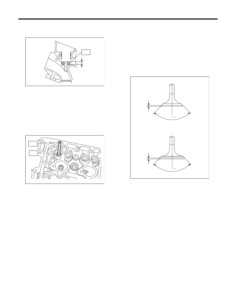
(6) Check the valve guide protrusion.
Valve guide protrusion L:
11.4 — 11.8 mm (0.449 — 0.465 in)
(7) Ream the inside of valve guide using ST.
Put the ST in valve guide, and rotate the ST
slowly clockwise while pushing it lightly. Bring
the ST back while rotating it clockwise.
ST
499765900
VALVE GUIDE REAMER
NOTE:
• Apply engine oil to the ST when reaming.
• If the inner surface of valve guide is damaged,
the edge of ST should be slightly ground with oil
stone.
• If the inner surface of valve guide becomes lus-
trous and the ST does not chip, use a new ST or
remedy the ST.
(8) After reaming, clean the valve guide to re-
move chips.
(9) Recheck the contact condition between
valve and valve seat after replacing the valve
guide.
4. INTAKE AND EXHAUST VALVE
1) Inspect the flange and stem of the valve, and re-
place if damaged, worn, or deformed, or if “H” is
outside of the standard.
Head edge thickness H:
Standard
Intake (A)
1.0 mm (0.039 in)
Exhaust (B)
1.2 mm (0.047 in)
2) Put a small amount of grinding compound on the
seat surface, and lap the valve and valve seat. In-
stall a new valve oil seal after lapping.
NOTE:
It is possible to differentiate between the intake
valve and the exhaust valve by their overall length.
Valve overall length:
Intake
99.7 mm (3.925 in)
Exhaust
105.2 mm (4.142 in)
ME-00757
ST
L
ME-00130
ST1
ST2
ME-02096
H
H
(B)
(A)
90 0
+1
90 0
+1
ME(H6DO)-63
Cylinder Head
MECHANICAL
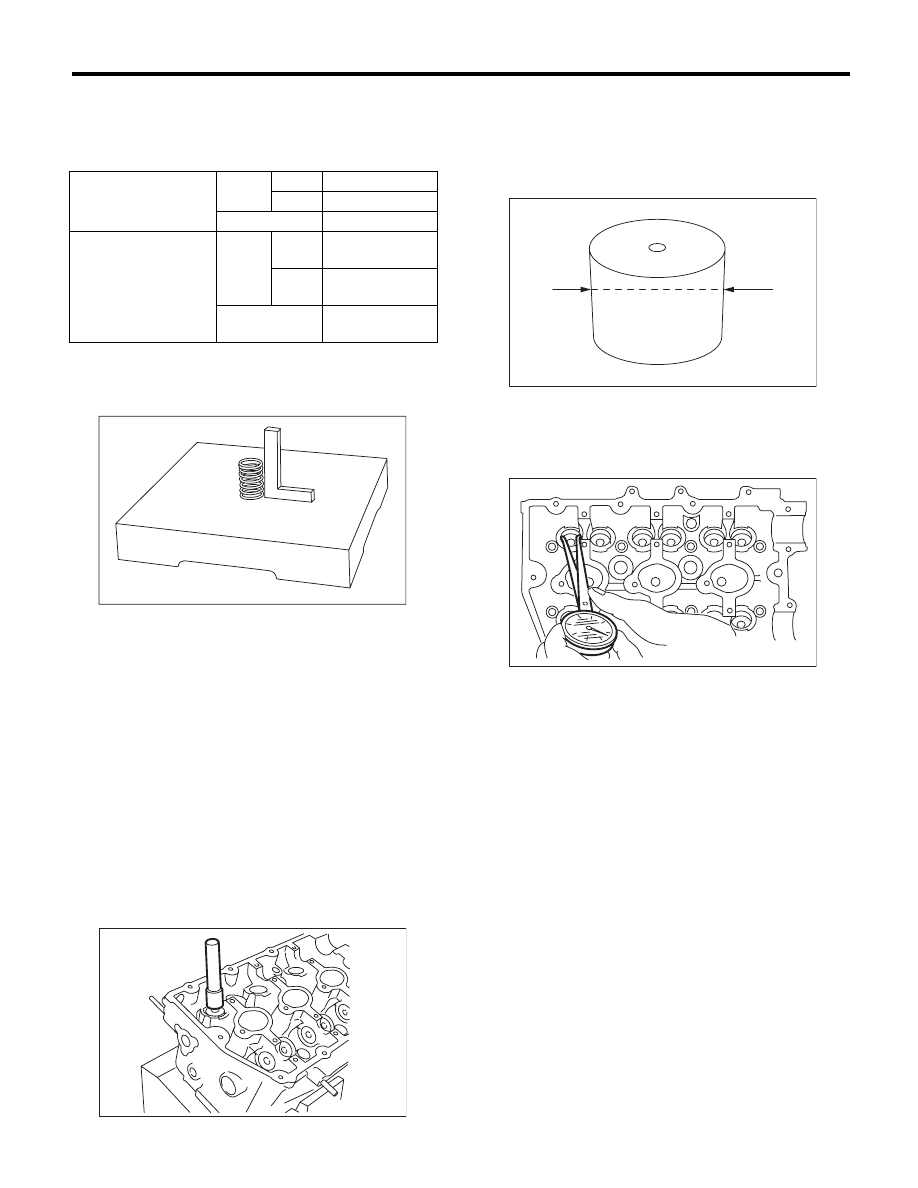
5. VALVE SPRING
1) Check the valve springs for damage, free length,
and tension. Replace the valve spring if it is not
within the standard value presented in the table.
2) To measure the squareness of the valve spring,
stand the valve spring on a surface plate and measure
its deflection at the top of the spring using a try square.
6. INTAKE AND EXHAUST VALVE OIL SEAL
1) For the following, replace the oil seal with a new
part.
• When the lip is damaged
• When the spring is out of the specified position
• When readjusting the surfaces of valve and
valve seat
• When replacing the valve guide
2) Set the cylinder head on ST1.
3) Using the ST2, press-fit the oil seal.
ST1
18250AA010 CYLINDER HEAD TABLE
ST2
499585500
VALVE OIL SEAL GUIDE
NOTE:
• Apply engine oil to oil seal before press-fitting.
• When press-fitting the oil seal, do not use a ham-
mer to strike in.
7. VALVE LIFTER
1) Check the valve lifter visually.
2) Measure the outer diameter of valve lifter.
Outer diameter:
32.959 — 32.975 mm (1.2976 — 1.2982 in)
3) Measure the inner diameter of valve lifter hole of
cylinder head.
Inner diameter:
32.994 — 33.016 mm (1.2990 — 1.2998 in)
NOTE:
If difference between outer diameter of valve lifter
and inner diameter of valve lifter hole is out of the
standard or offset wearing is emitted, replace the
cylinder head.
Standard:
0.019 — 0.057 mm (0.0007 — 0.0022 in)
Free length
mm (in)
Intake
Inner
39.55 (1.5571)
Outer
41.18 (1.6213)
Exhaust
46.32 (1.8236)
Squareness
Intake
Inner
2.5°, 1.7 mm
(0.067 in) or less
Outer
2.5°, 1.8 mm
(0.071 in) or less
Exhaust
2.5°, 2.0 mm
(0.079 in) or less
ME-00132
ME-03108
ME-00134
ME-03109
ME(H6DO)-64
Cylinder Block
MECHANICAL
21.Cylinder Block
A: REMOVAL
NOTE:
Before conducting this procedure, drain the engine
oil completely.
1) Remove the V-belts. <Ref. to ME(H6DO)-42,
REMOVAL, V-belt.>
2) Remove the crank pulley. <Ref. to ME(H6DO)-
43, REMOVAL, Crank Pulley.>
3) Remove the front chain cover. <Ref. to
ME(H6DO)-44, REMOVAL, Front Chain Cover.>
4) Remove the timing chain assembly. <Ref. to
ME(H6DO)-46, REMOVAL, Timing Chain Assem-
bly.>
5) Remove the cam sprocket. <Ref. to ME(H6DO)-
51, REMOVAL, Cam Sprocket.>
6) Remove the crank sprocket. <Ref. to
ME(H6DO)-52, REMOVAL, Crank Sprocket.>
7) Remove the rear chain cover. <Ref. to
ME(H6DO)-53, REMOVAL, Rear Chain Cover.>
8) Remove the camshaft. <Ref. to ME(H6DO)-55,
REMOVAL, Camshaft.>
9) Remove the cylinder head. <Ref. to ME(H6DO)-
59, REMOVAL, Cylinder Head.>
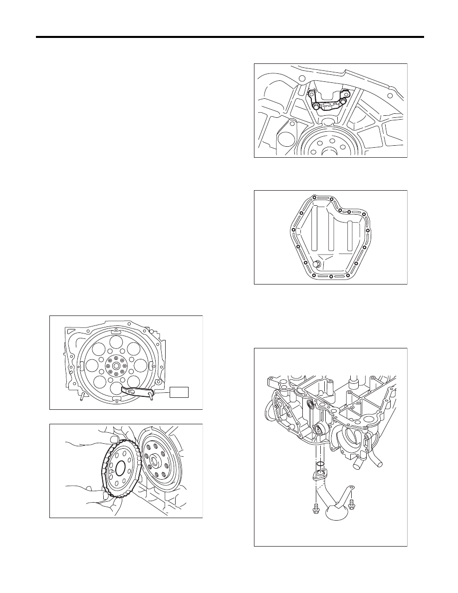
10) Use the ST to lock the crankshaft, and remove
the drive plate.
ST1
498497100
CRANKSHAFT STOPPER
ST2
499057000
TORX PLUS
®
11) Remove the crankshaft position sensor plate.
12) Remove the crankshaft position sensor brack-
et.
13) Rotate the engine to set oil pan upper.
14) Remove the bolts which secure oil pan lower to
oil pan upper.
15) Insert an oil pan cutter blade between cylinder
block-to-oil pan clearance and remove the oil pan.
CAUTION:
Do not use a screwdriver or similar tools in
place of oil pan cutter.
16) Remove the oil strainer.
ST
ME-00557
ME-00558
ME-00559
ME-00560
LU-02108
ME(H6DO)-65
Cylinder Block
MECHANICAL
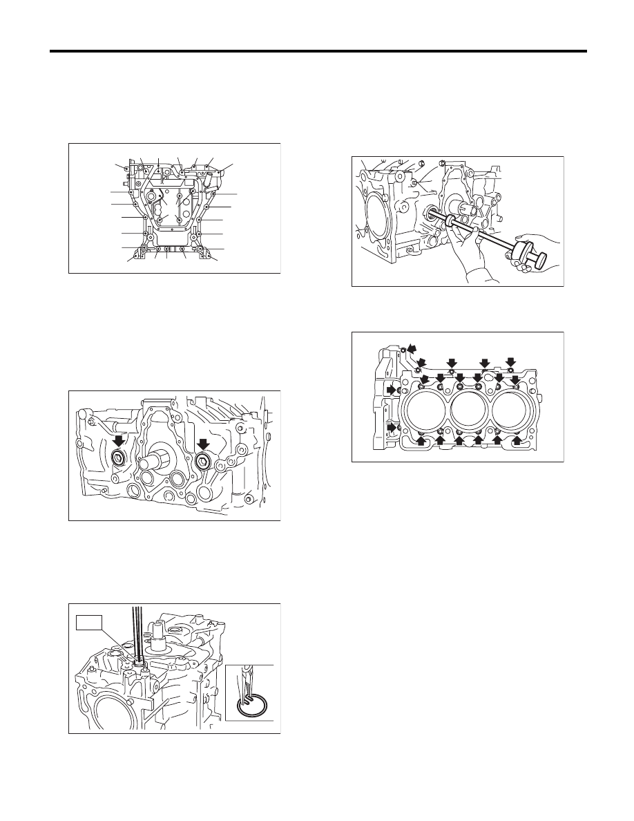
17) Remove the bolts which install oil pan upper
onto cylinder block.
NOTE:
Installation bolt has five different sizes. To prevent
the confusion in installation, keep these bolts on
container individually.
18) Remove the service hole cover and service
hole plugs using a hexagon wrench.
19) Rotate the crankshaft to bring #1 and #2 pis-
tons to bottom dead center position, then, using the
ST, remove the piston snap ring through service
hole of #1 and #2 cylinders.
ST
18233AA000
PISTON PIN SNAP RING
PLIERS
20) Draw out the piston pin from #1 and #2 pistons
using ST.
ST
499097700
PISTON PIN REMOVER
ASSY
NOTE:
Be careful not to confuse the original combination
of piston, piston pin and cylinder.
21) Similarly remove the piston pins from #3, #4,
#5, and #6 pistons.
22) Remove the cylinder block connecting bolts.
23) Separate the cylinder block (LH) and (RH).
NOTE:
When separating the cylinder block, do not allow
the connecting rod to fall or damage the cylinder
block.
24) Remove the rear oil seal.
25) Remove the crankshaft together with connect-
ing rod.
26) Remove the crankshaft bearings from cylinder
block using a hammer handle.
NOTE:
• Be careful not to confuse the crankshaft bearing
combination.
• Press the bearing at the end opposite to locking
lip.
27) Draw out each piston from cylinder block using
wooden bar or hammer handle.
NOTE:
Be careful not to confuse the original combination
of piston and cylinder.
(A) M8 × 40
(B) M8 × 65
(C) M8 × 85
(D) M8 × 130.5
(E) M8 × 24
ME-02065
(D)
(E)
(A)
(A)
(A)
(A)
(A)
(A)
(A)
(E)
(A)
(A)
(A)
(C)
(B)
(A)
(D)
(A)
(A)
(A)
(A)
(A)
(B)
ME-00563
ME-02603
ST
ME-00565
ME-00566
Нет комментариевНе стесняйтесь поделиться с нами вашим ценным мнением.
Текст