Subaru Legacy IV (2008 year). Service manual — part 731
5AT-48
Transmission Mounting System
AUTOMATIC TRANSMISSION
B: INSTALLATION
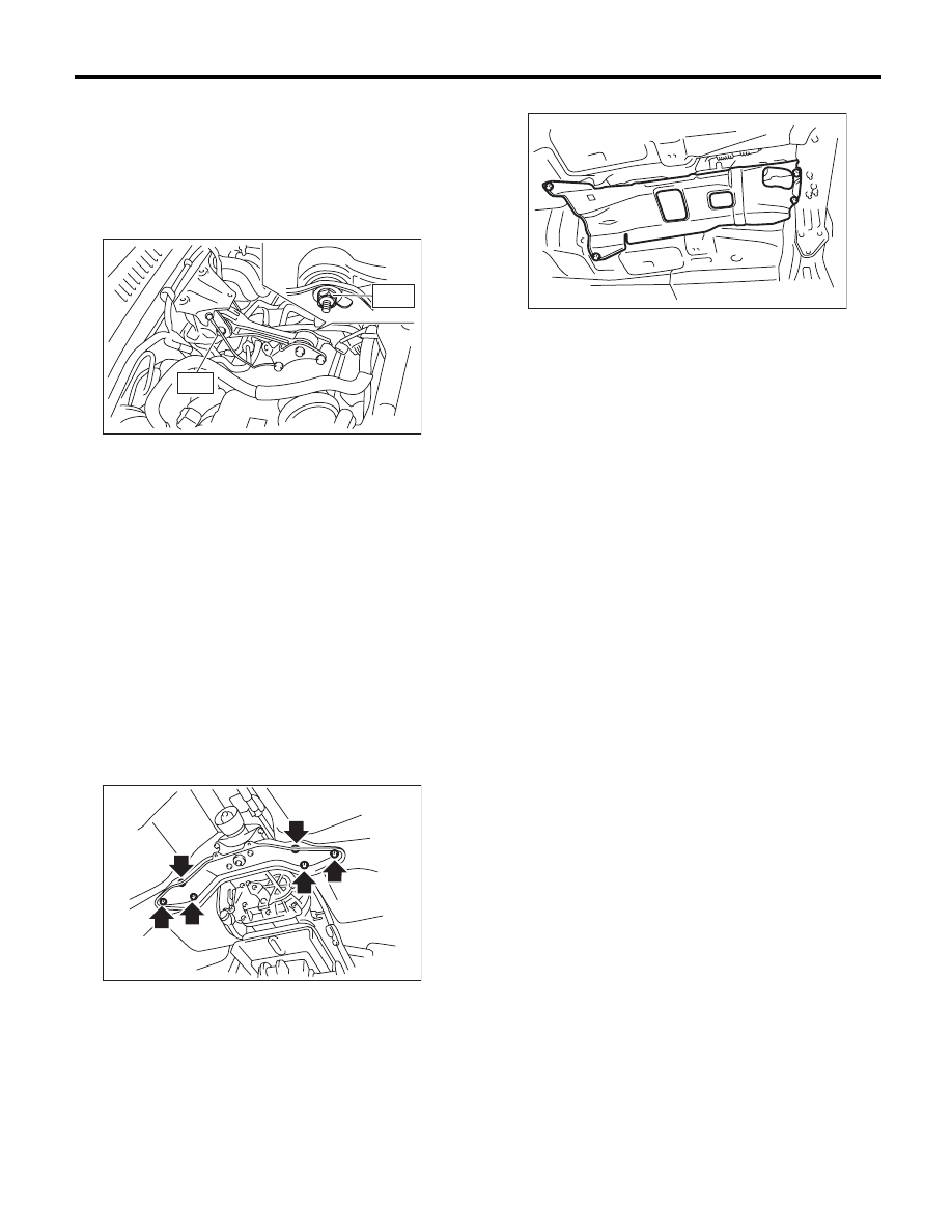
1. PITCHING STOPPER
1) Install the pitching stopper.
Tightening torque:
T1: 50 N·m (5.1 kgf-m, 36.9 ft-lb)
T2: 58 N·m (5.9 kgf-m, 42.8 ft-lb)
2) Install the intercooler. (Turbo model)
<Ref. to IN(H4DOTC)-13, INSTALLATION, Inter-
cooler.>
3) Install the air intake chamber. (Non-turbo model)
<Ref. to IN(H6DO)-7, INSTALLATION, Air Intake
Chamber.>
4) Connect the ground cable to battery.
2. TRANSMISSION REAR CROSSMEMBER &
REAR CUSHION RUBBER
1) Install the rear cushion rubber to the transmis-
sion.
Tightening torque:
35 N·m (3.6 kgf-m, 25.8 ft-lb)
2) Install the crossmember.
Tightening torque:
75 N·m (7.6 kgf-m, 55.3 ft-lb)
3) Remove the transmission jack.
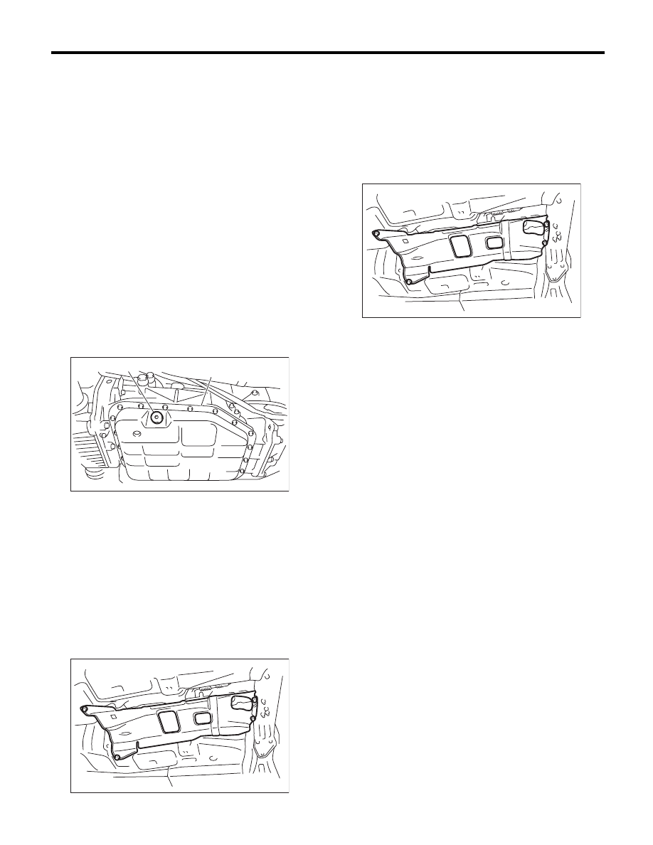
4) Install the heat shield cover.
5) Install the center, rear exhaust pipes and the
muffler. (Turbo model)
<Ref. to EX(H4DOTC)-9, INSTALLATION, Center
Exhaust Pipe.> <Ref. to EX(H4DOTC)-13, IN-
STALLATION, Rear Exhaust Pipe.> <Ref. to
EX(H4DOTC)-14, INSTALLATION, Muffler.>
6) Install the front exhaust pipe, rear exhaust pipe
and muffler. (Non-turbo model) <Ref. to
EX(H6DO)-5, INSTALLATION, Front Exhaust
Pipe.> <Ref. to EX(H6DO)-8, INSTALLATION,
Rear Exhaust Pipe.> <Ref. to EX(H6DO)-9, IN-
STALLATION, Muffler.>
7) Connect the ground cable to battery.
C: INSPECTION
Repair or replace parts if the results of the inspec-
tion below are not satisfied.
1. PITCHING STOPPER
Check pitching stopper for bends or damage.
Check that there are no cracks, hardening or dam-
age on rubber parts.
2. TRANSMISSION REAR CROSSMEMBER &
REAR CUSHION RUBBER
Check crossmember for bends or damage. Check
that there are no cracks, hardening, or damage on
cushion rubbers.
T2
T1
AT-03874
AT-01377
AT-01331
5AT-49
Extension Case Oil Seal
AUTOMATIC TRANSMISSION
11.Extension Case Oil Seal
A: INSPECTION
Inspect there is no ATF leakage from the joint of
transmission and propeller shaft. If a leak is found,
replace the oil seal. <Ref. to 5AT-49, REPLACE-
MENT, Extension Case Oil Seal.>
B: REPLACEMENT
1) Lift up the vehicle.
2) Clean the transmission exterior.
3) Remove the ATF drain plug to drain ATF.
CAUTION:
Immediately after the vehicle has been running
or after idling for a long time, the ATF will be
hot. Be careful not to burn yourself.
4) Tighten the ATF drain plug.
NOTE:
Use a new gasket.
Tightening torque:
20 N·m (2.0 kgf-m, 14.8 ft-lb)
5) Remove the rear exhaust pipe and muffler. (Tur-
bo model) <Ref. to EX(H4DOTC)-12, REMOVAL,
Rear Exhaust Pipe.> <Ref. to EX(H4DOTC)-14,
REMOVAL, Muffler.>
6) Remove the rear exhaust pipe and muffler.
(Non-turbo model) <Ref. to EX(H6DO)-7, REMOV-
AL, Rear Exhaust Pipe.> <Ref. to EX(H6DO)-9,
REMOVAL, Muffler.>
7) Remove the heat shield cover.
8) Remove the propeller shaft. <Ref. to DS-10, RE-
MOVAL, Propeller Shaft.>
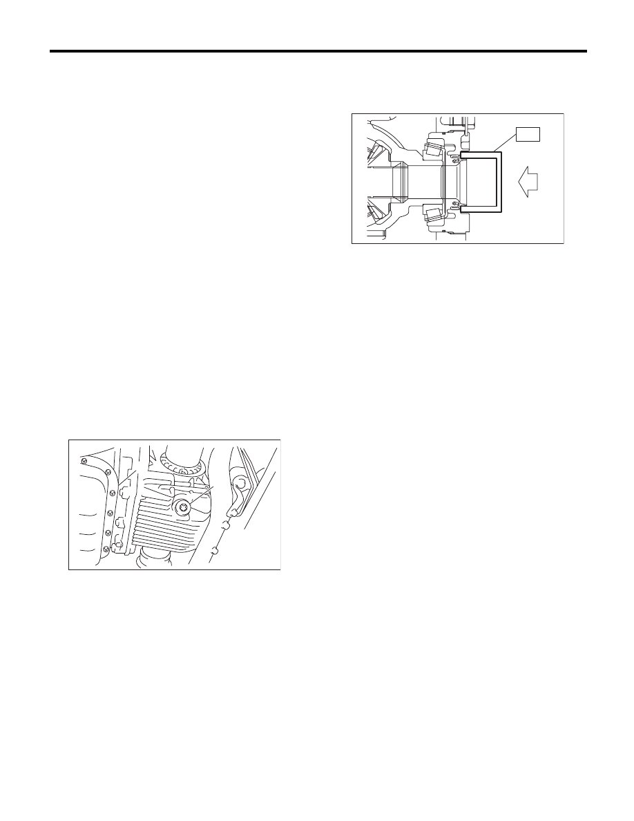
9) Using the ST, remove the oil seal.
ST
398527700
PULLER ASSY
10) Using the ST, install the oil seal.
ST
498057300
INSTALLER
11) Install the propeller shaft. <Ref. to DS-11, IN-
STALLATION, Propeller Shaft.>
12) Install the heat shield cover.
13) Install the rear exhaust pipe and muffler. (Turbo
model) <Ref. to EX(H4DOTC)-13, INSTALLA-
TION, Rear Exhaust Pipe.> <Ref. to EX(H4DOTC)-
14, INSTALLATION, Muffler.>
14) Install the rear exhaust pipe and muffler. (Non-
turbo model) <Ref. to EX(H6DO)-8, INSTALLA-
TION, Rear Exhaust Pipe.> <Ref. to EX(H6DO)-9,
INSTALLATION, Muffler.>
15) Pour ATF from the oil charge pipe. <Ref. to
5AT-28, Automatic Transmission Fluid.>
16) Check the level and leaks of the ATF. <Ref. to
5AT-28, INSPECTION, Automatic Transmission
Fluid.>
(A) Oil pan
(B) ATF drain plug
(A)
AT-03126
(B)
AT-01331
AT-01331
5AT-50
Differential Side Retainer Oil Seal
AUTOMATIC TRANSMISSION
12.Differential Side Retainer Oil
Seal
A: INSPECTION
Check for leakage of gear oil from differential side
retainer oil seal part. If there is an oil leak, replace
the oil seal.
B: REPLACEMENT
1) Lift up the vehicle.
2) Remove the front exhaust pipe and center ex-
haust pipe. (Turbo model) <Ref. to EX(H4DOTC)-
5, REMOVAL, Front Exhaust Pipe.> <Ref. to
EX(H4DOTC)-7, REMOVAL, Center Exhaust
Pipe.>
3) Remove the front exhaust pipe. (Non-turbo mod-
el) <Ref. to EX(H6DO)-4, REMOVAL, Front Ex-
haust Pipe.>
4) Remove the differential gear oil drain plug using
TORX
®
bit T70, and then drain differential gear oil.
CAUTION:
• Immediately after the vehicle has been run-
ning or after idling for a long time, the differen-
tial gear oil will be hot. Be careful not to burn
yourself.
• Be careful not to spill the differential gear oil
on exhaust pipe to prevent it from emitting
smoke or fire. If differential gear oil is spilled on
the exhaust pipe, wipe it off completely.
5) Tighten the differential gear oil drain plug.
NOTE:
Use a new gasket.
Tightening torque:
70 N·m (7.1 kgf-m, 51.6 ft-lb)
6) Separate the front drive shaft from the transmis-
sion. <Ref. to DS-22, REMOVAL, Front Drive
Shaft.>
7) Remove the differential side retainer oil seal us-
ing driver wrapped with vinyl tape etc.
8) Using the ST, install the differential side retainer
oil seal by lightly tapping with a hammer.
ST
18675AA000
DIFFERENTIAL SIDE OIL
SEAL INSTALLER
9) Apply oil to the oil seal lips.
10) Install the front drive shaft. <Ref. to DS-22, IN-
STALLATION, Front Drive Shaft.>
11) Install the front exhaust pipe and the center ex-
haust pipe. (Turbo model) <Ref. to EX(H4DOTC)-
6, INSTALLATION, Front Exhaust Pipe.> <Ref. to
EX(H4DOTC)-9, INSTALLATION, Center Exhaust
Pipe.>
12) Install the front exhaust pipe. (Non-turbo mod-
el) <Ref. to EX(H6DO)-5, INSTALLATION, Front
Exhaust Pipe.>
13) Lower the vehicle.
14) Pour gear oil through the level gauge hole.
<Ref. to 5AT-30, Differential Gear Oil.>
15) Check the level of differential gear oil. <Ref. to
5AT-30, INSPECTION, Differential Gear Oil.>
(A) Oil pan
(B) Differential gear oil drain plug
(B)
AT-01362
(A)
AT-00029
ST
5AT-51
Inhibitor Switch
AUTOMATIC TRANSMISSION
13.Inhibitor Switch
A: INSPECTION
Inhibitor switch cannot be checked, because the in-
hibitor switch is installed on control valve assembly.
When a malfunction occurs, refer to 5AT (diag)
section. <Ref. to 5AT(diag)-35, DTC P0705
TRANSMISSION RANGE SENSOR CIRCUIT
(PRNDL INPUT), Diagnostic Procedure with Diag-
nostic Trouble Code (DTC).>
Нет комментариевНе стесняйтесь поделиться с нами вашим ценным мнением.
Текст