Subaru Legacy IV (2008 year). Service manual — part 831
CL-10
General Description
CLUTCH SYSTEM
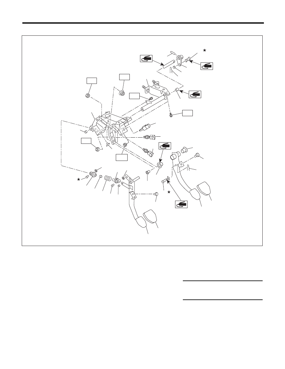
5. CLUTCH PEDAL
(1)
Stopper
(10)
Bushing C
(19)
Pedal bracket
(2)
Bushing
(11)
Clutch clevis pin
(20)
Clutch master cylinder bracket
(3)
Spring pin
(12)
Assist rod A
(21)
Lever
(4)
Snap pin
(13)
Clip
(22)
Clutch switch (Clutch start)
(5)
Brake pedal pad
(14)
Assist spring
(6)
Brake pedal
(15)
Assist bushing
Tightening torque:N·m (kgf-m, ft-lb)
(7)
Clevis pin
(16)
Assist rod B
T1: 8 (0.8, 5.9)
(8)
Clutch pedal pad
(17)
Clutch switch (Cruise control)
T2: 18 (1.8, 13.3)
(9)
Clutch pedal
(18)
Stop light switch
CL-00625
(7)
(7)
(7)
T1
T1
T2
T2
T2
(11)
(4)
(2)
(3)
(22)
(21)
(20)
(1)
(1)
(1)
(2)
(2)
(6)
(9)
(10)
(12)
(15)
(16)
(17)
(19)
(18)
(14)
(13)
(5)
(2)
(8)
(4)
(13)
(10)
(10)
T1
CL-11
General Description
CLUTCH SYSTEM
C: CAUTION
• Wear appropriate work clothing, including a cap,
protective goggles and protective shoes when per-
forming any work.
• Remove contamination including dirt and corro-
sion before removal, installation or disassembly.
• Keep the disassembled parts in order and pro-
tect them from dust and dirt.
• Before removal, installation or disassembly, be
sure to clarify the failure. Avoid unnecessary re-
moval, installation, disassembly and replacement.
• Vehicle components are extremely hot after driv-
ing. Be wary of receiving burns from heated parts.
• Use SUBARU genuine fluid, grease etc. or
equivalent. Do not mix fluid, grease, etc. of different
grades or manufacturers.
• Be sure to tighten fasteners including bolts and
nuts to the specified torque.
• Place shop jacks or rigid racks at the specified
points.
• Apply grease onto sliding or revolving surfaces
before installation.
• Before installing O-rings or snap rings, apply suf-
ficient amount of fluid to avoid damage and defor-
mation.
• Before securing a part in a vise, place cushioning
material such as wood blocks, aluminum plate or
cloth between the part and the vise.
• Keep fluids away from the vehicle body. If any
fluid contacts the vehicle body, immediately flush
the area with water.
CL-12
General Description
CLUTCH SYSTEM
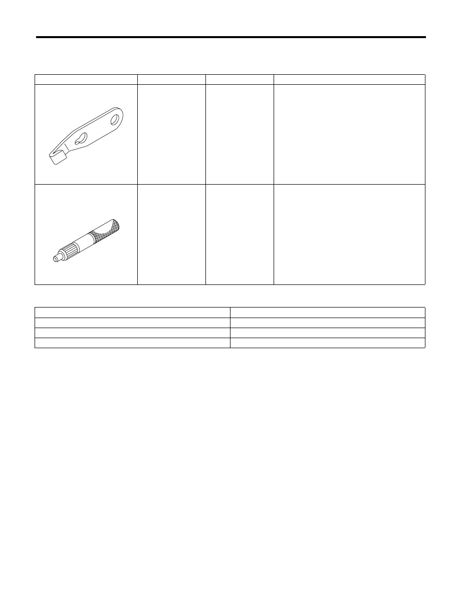
D: PREPARATION TOOL
1. SPECIAL TOOL
2. GENERAL TOOL
ILLUSTRATION
TOOL NUMBER
DESCRIPTION
REMARKS
498497100
CRANKSHAFT
STOPPER
Used for stopping rotation of the flywheel.
499747100
CLUTCH DISC
GUIDE
Used when installing the clutch disc to the fly-
wheel.
TOOL NAME
REMARKS
Circuit tester
Used for measuring resistance, voltage and ampere.
Dial gauge
Used for measuring clutch disc run-out.
Depth gauge
Used for measuring clutch disc wear.
ST-498497100
ST-499747100
CL-13
Clutch Disc and Cover
CLUTCH SYSTEM
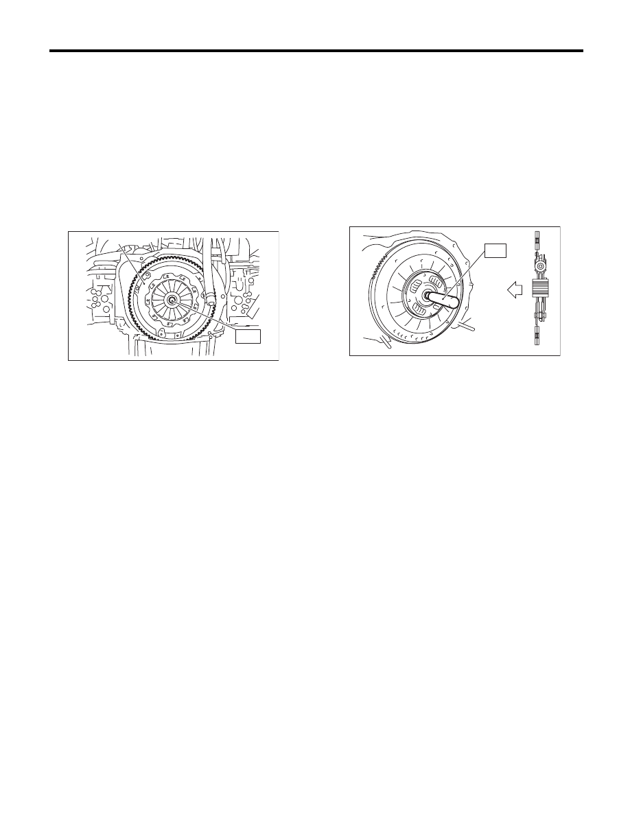
2. Clutch Disc and Cover
A: REMOVAL
NOTE:
The illustration below is for a 5MT non-turbo model.
However, perform the same procedures for models
other than 5MT non-turbo model as well.
1) Remove the transmission assembly from vehicle
body. <Ref. to 5MT-24, REMOVAL, Manual Trans-
mission Assembly.> <Ref. to 6MT-32, REMOVAL,
Manual Transmission Assembly.>
2) Insert the ST on the flywheel.
ST
499747100
CLUTCH DISC GUIDE
3) Remove the clutch cover and clutch disc.
NOTE:
• Take care not to allow oil to touch the clutch disc
face.
• Do not disassemble the clutch cover or clutch
disc.
B: INSTALLATION
NOTE:
The illustration below is for a 5MT non-turbo model.
However, perform the same procedures for models
other than 5MT non-turbo model as well.
1) Insert the ST into the clutch disc and attach to
the flywheel by inserting the ST end into pilot bear-
ing.
NOTE:
When installing the clutch disc, be careful to attach
in the correct direction.
ST
499747100
CLUTCH DISC GUIDE
(A) Clutch cover
CL-00011
( A )
S T
(A) Flywheel side
(A)
ST
CL-00012
Нет комментариевНе стесняйтесь поделиться с нами вашим ценным мнением.
Текст