Subaru Legacy IV (2008 year). Service manual — part 414

GD(H4DOTC)-106
Diagnostic Trouble Code (DTC) Detecting Criteria
GENERAL DESCRIPTION
3. ENABLE CONDITION
4. GENERAL DRIVING CYCLE
Perform the diagnosis only once at a constant 60 km/h (37.3 MPH) or higher.
5. DIAGNOSTIC METHOD
After establishing the execution conditions, calculate the front oxygen (A/F) sensor lambda deviation cumu-
lative value (
6 |(sglmd
n
– sglmd
n–1
)|) and rear oxygen sensor output voltage deviation cumulative value (
6
|(ro2sad
n
– ro2sad
n–1
)|) per 32 milliseconds × 4 , and when the front oxygen (A/F) sensor lambda deviation
cumulative value (
6 |(sglmd
n
– sglmd
n–1
)|) becomes the predetermined value or more, calculate the diag-
nostic value.
• Abnormality Judgement
If the duration of time while the following conditions are met is within the time indicated, judge as NG.
Time Needed for Diagnosis: 30 — 55 seconds
Malfunction Indicator Light Illumination: Illuminates when malfunction occurs in 2 continuous driving cy-
cles.
• Normality Judgement
Judge as OK and clear the NG if the continuous time while the following conditions are established is within
the predetermined time.
Time Needed for Diagnosis: 30 — 55 seconds
Secondary Parameters
Enable Conditions
Battery voltage
t 10.9 V
Atmospheric pressure
t 75 kPa (563 mmHg, 22.2 inHg)
Engine coolant temperature
t 70 °C (158 °F)
Estimated catalyst temperature
t 500 °C (932 °F)
Misfire detection every 200 rotations
< 5 time(s)
Learning value of evaporation gas density
< 0.2
Sub feedback
In operation
Evaporative system diagnosis
Not in operation
Time of difference (< 0.10) between actual
lambda and target lambda
t 1000 ms
Vehicle speed
> 60 km/h (37.3 MPH)
Amount of intake air
t 10 g/s (0.35 oz/s)
and
< 40 g/s (1.41 oz/s)
Engine load change every 0.5 engine revs.
< 0.02 g/rev (0 oz/rev)
Rear oxygen output change from 660 mV or
less to 660 mV or more
Experienced after fuel cut
Elapsed time after starting the engine
t 200 s
Purge execution calculated time
t 5 s
Judgement Value
Malfunction Criteria
Threshold Value
6 |(ro2sad
n
– ro2sad
n–1
)| /
6 |(sglmd
n
–
sglmd
n–1
)|
> 11 (AT model)
> 9 (MT model)
Judgement Value
Malfunction Criteria
Threshold Value
6 |(ro2sad
n
– ro2sad
n–1
)| /
6 |(sglmd
n
–
sglmd
n–1
)|
d 11 (AT model)
d 9 (MT model)
GD(H4DOTC)-107
Diagnostic Trouble Code (DTC) Detecting Criteria
GENERAL DESCRIPTION
BK:DTC P0441 EVAPORATIVE EMISSION SYSTEM INCORRECT PURGE FLOW
1. OUTLINE OF DIAGNOSIS
NOTE:
For the detection standard, refer to DTC P0442. <Ref. to GD(H4DOTC)-108, DTC P0442 EVAPORATIVE
EMISSION CONTROL SYSTEM LEAK DETECTED (SMALL LEAK), Diagnostic Trouble Code (DTC) De-
tecting Criteria.>
GD(H4DOTC)-108
Diagnostic Trouble Code (DTC) Detecting Criteria
GENERAL DESCRIPTION
BL:DTC P0442 EVAPORATIVE EMISSION CONTROL SYSTEM LEAK DETECTED
(SMALL LEAK)
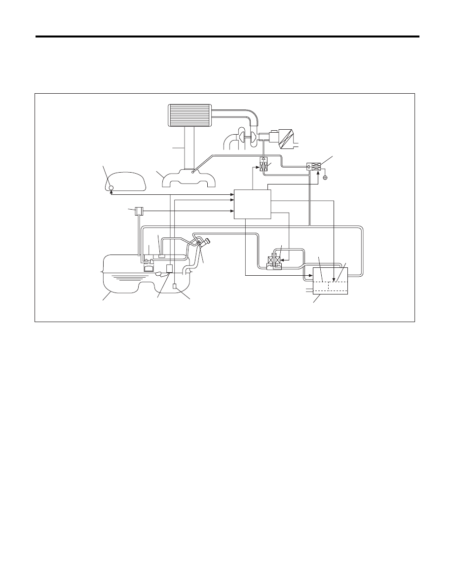
1. OUTLINE OF DIAGNOSIS
Check if there is a leakage in fuel system or not, and perform the function diagnosis of valve.
In this system diagnosis, check for leakage and valve function is conducted by changing the fuel tank pres-
sure and monitoring the pressure change using the fuel tank pressure sensor. When in 0.04 inch diagnosis,
perform in the order of mode Z
o mode A o mode B o mode C and mode D; When in 0.02 inch diagnosis,
perform in the order of mode A
o mode B o mode C o mode D and mode E.
(1)
Fuel gauge
(7)
Canister
(13)
Fuel level sensor
(2)
Intake manifold
(8)
Pressure control valve
(14)
Fuel tank
(3)
Throttle body
(9)
Drain valve
(15)
Fuel cut valve
(4)
Purge control solenoid valve
(10)
Drain filter
(16)
Fuel tank pressure sensor
(5)
Purge control solenoid valve 2
(11)
Shut-off valve
(17)
Vent valve
(6)
Engine control module (ECM)
(12)
Fuel temperature sensor
(1)
(2)
(3)
(6)
(8)
(9)
(10)
(4)
(5)
(7)
(12)
(11)
(13)
(14)
(17)
(15)
(16)
EN-05372
GD(H4DOTC)-109
Diagnostic Trouble Code (DTC) Detecting Criteria
GENERAL DESCRIPTION
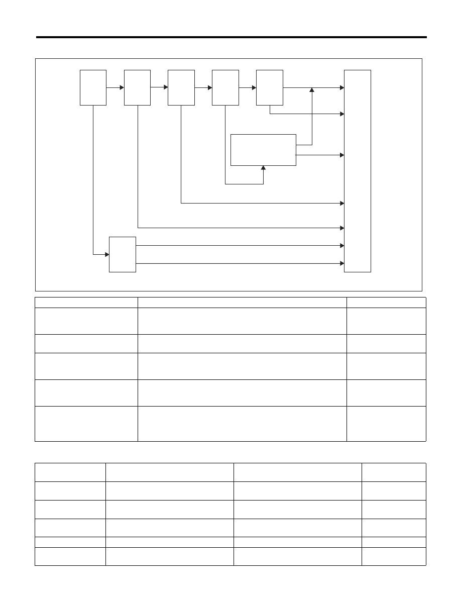
0.04-inch Diagnosis
Mode Table for Evaporative Emission Control System Diagnosis
Mode
Mode Description
Diagnosis Period
Mode Z
(Purge control solenoid valve
opening failure diagnosis)
Perform purge control solenoid valve opening failure diagnosis from
the size of tank pressure variation from diagnosis start.
0 ms + 3000 ms — 0 ms
+ 3000 ms + 13000 ms
Mode A
(Estimated evaporation amount)
Calculate the tank pressure change amount (P1).
10000 ms
Mode B
(Sealed negative pressure,
large leakage judgement)
Decrease the pressure in the tank to the target value by introducing
the intake manifold pressure to the fuel tank.
If the tank pressure cannot be reduced, it is diagnosed as large leak.
0 — 10000 ms
+ 25000 ms
Mode C
(Pressure increase check,
advanced OK judgement)
Wait until the tank pressure returns to the target (start level of P2
calculation). If the tank pressure does not become the value, make
advanced OK judgement.
0 — 17000 ms
Mode D
(Negative pressure variation
measurement, evaporation
leakage diagnosis)
Calculate the tank pressure variation (P2), and obtain the diagnostic
value using P1 found in Mode A.
Perform the evaporation diagnosis using the diagnostic value.
0 ms + 10000 ms
Mode
Behavior of tank internal pressure under
normal conditions
Diagnostic item
DTC
Mode Z
Roughly the same as barometric pres-
sure (Same as 0 kPa (0 mmHg, 0 inHg))
Purge control solenoid valve is judged to
be open.
P0457
Mode A
Pressure is in proportion to amount of
evaporative emission.
—
None
Mode B
Negative pressure is formed due to
intake manifold negative pressure
Large leak
P0457
Mode C
Reaches target pressure
—
None
Mode D
Pressure change is small.
EVAP system large leak determination.
[1.0 mm (0.04 in)]
P0442
Mode
Z
Mode
A
Mode
B
Mode
C
Mode
D
Parge control
solenoid velve2
blockade diagnosis
OK
NG
OK
OK
OK
OK
NG
Early OK
Large leakage judgement
Cancel
Mode
Z
Extend
NG
NG
OK
END
EN-05590
OK
Нет комментариевНе стесняйтесь поделиться с нами вашим ценным мнением.
Текст