Subaru Legacy IV (2008 year). Service manual — part 263
ME(H4DOTC)-32
Engine Assembly
MECHANICAL
27) Separate the clutch release fork from the re-
lease bearing. (6MT model)
(1) Remove the clutch operating cylinder from
the transmission.
(2) Remove the plug using a 10 mm hexagon
wrench.
(3) Screw-in the 6 mm dia. bolt into the release
fork shaft to remove.
(4) Raise the release fork, unlock the release
bearing tab, then remove the release fork.
NOTE:
Step (4) is required to avoid interference with the
engine when removing the engine from the trans-
mission.
28) Separate the torque converter clutch from drive
plate. (AT model)
(1) Remove the service hole plug.
(2) Insert the wrench into the crank pulley bolt
and rotate the crank pulley to remove the bolts
which hold torque converter clutch to drive
plate.
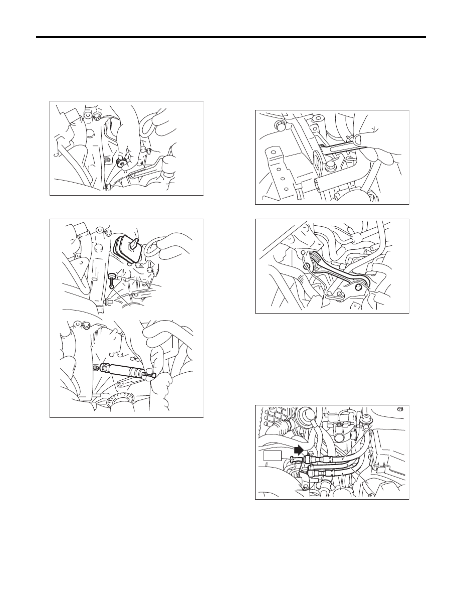
29) Remove the pitching stopper.
30) Attach ST to the fuel delivery pipe and push ST
in the direction of arrow mark to disconnect the fuel
delivery hose.
ST
42099AE000
QUICK CONNECTOR
RELEASE
CAUTION:
• Be careful not to spill fuel.
• Catch the fuel from hoses using a container
or cloth.
(A) Release fork shaft
(B) Bolt
ME-00042
ME-00043
(B)
(A)
(A) Fuel delivery hose
(B) Fuel return hose
(C) Evaporation hose
ME-00044
AT-03877
ME-03907
(B)
(C)
ST
(A)
ME(H4DOTC)-33
Engine Assembly
MECHANICAL
31) Disconnect the fuel return hose using the ST.
ST
18371AA000
CONNECTOR REMOVER
CAUTION:
• Be careful not to spill fuel.
• Catch the fuel from hoses using a container
or cloth.
(1) Attach ST to the fuel return pipe as shown in
the figure.
(2) Insert the front side of ST into the quick con-
nector.
(3) Insert the back side of ST into the quick con-
nector and push ST in the direction of arrow
mark to disconnect the fuel return hose.
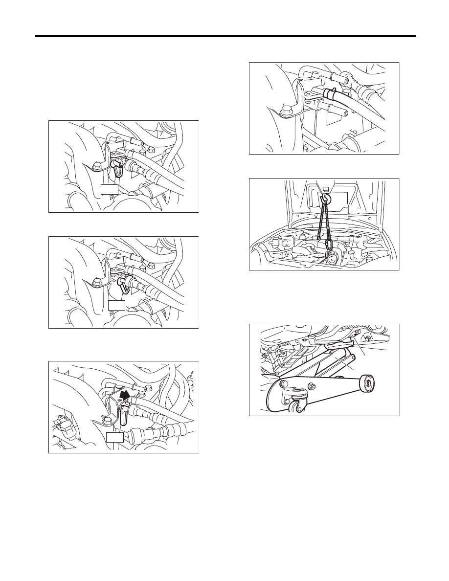
32) Remove the clip and disconnect the evapora-
tion hose from the fuel pipe.
33) Support the engine with a lifting device and
wire ropes.
34) Support the transmission with a garage jack.
CAUTION:
Be sure to perform this procedure to prevent
the transmission from lowering by its own
weight.
FU-03092
ST
FU-03113
ST
FU-03114
ST
(A) Transmission
(B) Garage jack
FU-03105
LU-00222
ME-00215
(B)
(A)
ME(H4DOTC)-34
Engine Assembly
MECHANICAL
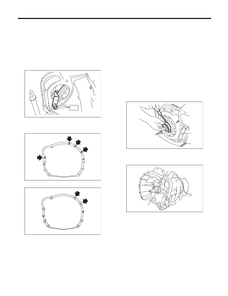
35) Separation of engine and transmission
CAUTION:
Before removing the engine away from trans-
mission, check to be sure no work has been
overlooked.
(1) Remove the starter. <Ref. to SC(H4SO)-6,
REMOVAL, Starter.>
(2) Attach the ST to the torque converter clutch
case. (AT model)
ST
498277200
STOPPER SET
(3) Remove the bolts which hold the upper side
of the transmission to the engine.
• AT model
• MT model
36) Remove the engine from vehicle.
(1) Slightly raise the engine.
(2) Raise the transmission with garage jack.
(3) Move the engine horizontally until main shaft
is withdrawn from clutch cover. (MT model)
(4) Slowly move the engine away from engine
compartment.
NOTE:
Be careful not to damage adjacent parts or body
panels with crank pulley, oil level gauge, etc.
37) Remove the engine mounting from the engine.
B: INSTALLATION
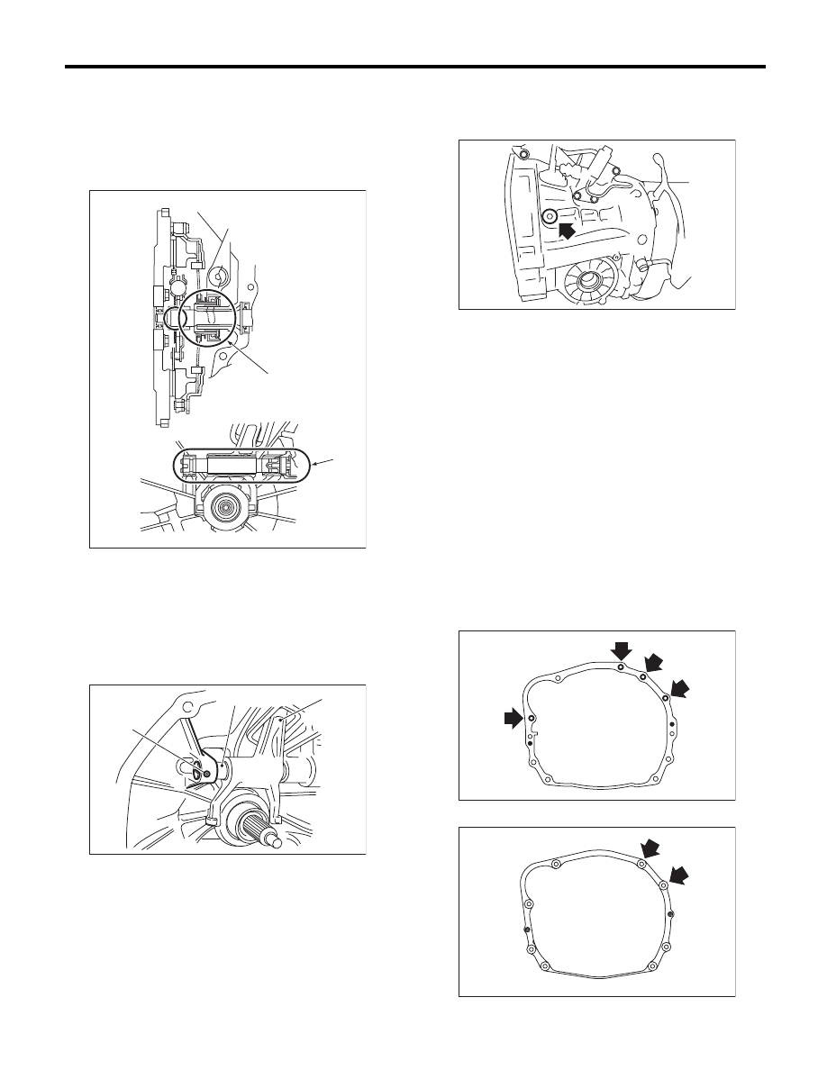
1) Install the clutch release fork and bearing to the
transmission. (6MT model)
(1) Use a flat tip screwdriver to remove the re-
lease bearing from the clutch cover.
(2) Install the release bearing to the transmission.
(3) Install the release fork into the release bear-
ing tab.
ST
ME-00217
ME-00491
MT-01524
(A) Release fork
(B) Release bearing
ME-00051
ME-02591
(A)
(B)
ME(H4DOTC)-35
Engine Assembly
MECHANICAL
(4) Apply grease to the specified areas.
Grease:
Spline part
NICHIMOLY N-130 or equivalent
Shaft part
KOPR-KOTE or equivalent
(5) Insert the release shaft to release fork.
NOTE:
Allow the cutout portion of release shaft to come
into contact with the spring pin.
(6) Tighten the plugs.
Tightening torque:
44 N·m (4.5 kgf-m, 32.5 ft-lb)
2) Install the engine mounting onto the engine.
Tightening torque:
35 N·m (3.6 kgf-m, 25.8 ft-lb)
3) Apply a small amount of grease to splines of
main shaft. (MT model)
Grease:
NICHIMOLY N-130 or equivalent
4) Position the engine in engine compartment and
align it with transmission.
NOTE:
Be careful not to damage adjacent parts or body
panels with crank pulley, oil level gauge, etc.
5) Tighten the bolts which hold upper side of trans-
mission to engine.
Tightening torque:
50 N·m (5.1 kgf-m, 36.9 ft-lb)
• AT model
• MT model
(A) Spline
(B) Shaft
(A) Release fork
(B) Release shaft
(C) Spring pin
CL-00304
(A)
(B)
ME-00054
(A)
(B)
(C)
ME-02592
ME-00491
MT-01524
Нет комментариевНе стесняйтесь поделиться с нами вашим ценным мнением.
Текст