Subaru Legacy IV (2008 year). Service manual — part 1179

LAN(diag)-50
Diagnostic Procedure with Diagnostic Trouble Code (DTC)
LAN SYSTEM (DIAGNOSTICS)
18
CHECK CONTROL MODULE.
1) Connect the steering angle sensor connec-
tor.
2) Using the Subaru Select Monitor, perform
the clear memory.
3) Disconnect the yaw rate sensor connector
(B230).
4) Turn the ignition switch to ON and read the
DTC of the body integrated unit. <Ref. to
LAN(diag)-12, READ DIAGNOSTIC TROUBLE
CODE (DTC), OPERATION, Subaru Select
Monitor.>
Is DTC U1201 displayed?
Go to step 19.
Check the yaw rate
sensor. <Ref. to
VDC(diag)-14,
HOW TO USE
SUBARU SELECT
MONITOR, OPER-
ATION, Subaru
Select Monitor.>
19
CHECK CONTROL MODULE.
1) Connect all the control module connectors.
2) Check the data of “Body Int. Unit Data” on
the current data display of ECM using Subaru
Select Monitor.
Is the “ON” displayed?
Go to step 20.
Replace the body
integrated unit.
<Ref. to SL-56,
REMOVAL, Body
Integrated Unit.>
20
CHECK CONTROL MODULE.
Check the data of “Body Int. Unit Count” on the
data display of ECM.
Is the “ON” displayed?
Inspect the ABS/
VDC CM and
ECM. <Ref. to
ABS(diag)-13,
HOW TO USE
SUBARU SELECT
MONITOR, OPER-
ATION, Subaru
Select Monitor.>
<Ref. to
VDC(diag)-14,
HOW TO USE
SUBARU SELECT
MONITOR, OPER-
ATION, Subaru
Select Monitor.>
<Ref. to
EN(H6DO)(diag)-
43, SUBARU
SELECT MONI-
TOR (NORMAL
MODE), OPERA-
TION, Read Diag-
nostic Trouble
Code (DTC).>
Replace the body
integrated unit.
<Ref. to SL-56,
REMOVAL, Body
Integrated Unit.>
Step
Check
Yes
No
LAN(diag)-51
Diagnostic Procedure with Diagnostic Trouble Code (DTC)
LAN SYSTEM (DIAGNOSTICS)
I:
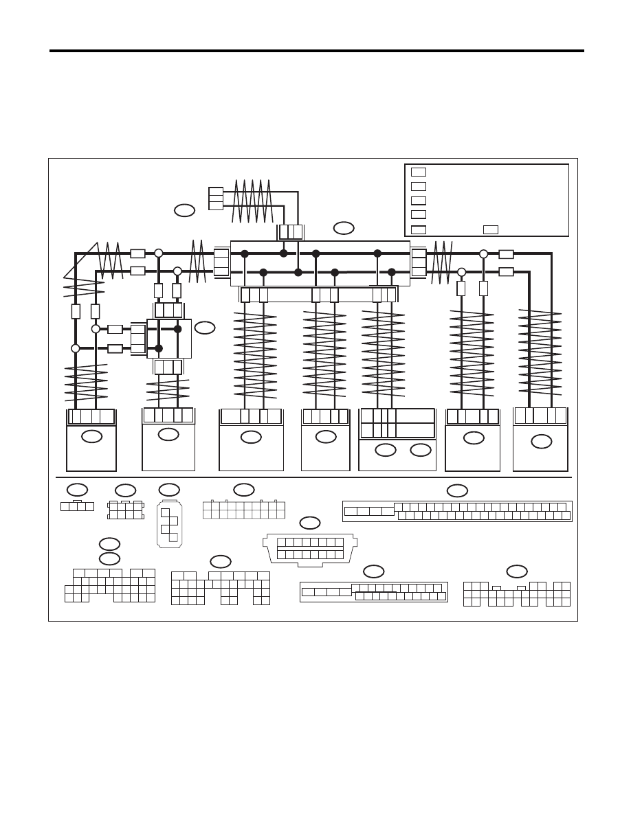
DTC U1202 CAN-HS BUS OFF
DTC DETECTING CONDITION:
• Find the unit or CAN line in which trouble occurs, and repair and replace it.
• Not received data and error data may be detected at the same time.
TROUBLE SYMPTOM:
“Er HC” is displayed in odo/trip meter. (Except for meter with MID)
WIRING DIAGRAM:
LAN00382
B40
1 2 3 4 5 6 7 8
9 10 11 12 13 14 15 16
B280
B:
5
4
6 7
8
2
1
9
3
10
22
23
11 12 13 14 15
24 25
26 27
16 17 18
28 29
19 20
21
30
B231
1 2 3 4
A: B54
16
10 11 12 13 14 15
25
24
30
9
8
7
17 18 19 20
28
21 22 23
29
32
31
1
2
3
4
5
6
27
26
33 34 35
B310
4 5 6 7 8 9
26 27 28 29 30
2 3
1
31 32 33 34 35 36
10 11
14 15 16 17 18 19
37 38 39 40
12 13
41 42 43 44 45 46
20 21
23
24
22
25
B230
1
2
3
4
B170
3 4
5 6
1 2
7 8
1 2 3 4 5 6 7 8 9 10
11 12 13 14 15 16 17 18 19 20
B365
B301
4 5 6 7 8 9
16 17 18 19 20
2 3
1
21 22 23 24 25 26
10 11
13
14
12
15
C: B136
B:
B55
5
6
7
2
1
3
4
29
10 11 12 13 14 15
25
24
16
30
9
8
17 18 19
20
28
21 22 23
32
31
26 27
33
34 35
2
3
B230
YAW RATE
SENSOR
B231
2
1
STEERING
ANGLE
SENSOR
VDCCM & H/U
B310
35
10
ECM
B136
27
35
B30
B20
BODY
INTEGRATED UNIT
B280
B:
6
14
B170
B365
B40
CAN JOINT
CONNEC-
TOR
CAN JOINT
CONNECTOR
DATA LINK
CONNECTOR
2
*
1
*
2
*
1
*
3
*
4
*
2
*
1
*
2
*
1
*
2
*
1
*
2
*
1
*
3
*
4
*
3
*
4
*
VDC
VDC
VDC
VDC
ABS
ABS
ABS
ABS
ABSCM & H/U
B301
26
11
VDC
ABS
ABS
TCM
B54
A:
4AT MODEL
5AT MODEL
B21
B20
A18
A17
B55
B:
VDC
*
1
*
2
*
3
*
4
: WITHOUT VDC
ABS
VDC
: TERMINAL No. OPTIONAL ARRANGEMENT
AMONG 1, 2, 3, 11, 12 AND 13
: TERMINAL No. OPTIONAL ARRANGEMENT
AMONG 8, 9, 10, 18, 19 AND 20
: TERMINAL No. OPTIONAL ARRANGEMENT
AMONG 1, 2, 5 AND 6
: TERMINAL No. OPTIONAL ARRANGEMENT
AMONG 3, 4, 7 AND 8
: WITH VDC

LAN(diag)-52
Diagnostic Procedure with Diagnostic Trouble Code (DTC)
LAN SYSTEM (DIAGNOSTICS)
Step
Check
Yes
No
1
CHECK DTC.
Check the DTC displayed in the body integrated
unit.
Is the DTC displayed a current
malfunction?
Check the connec-
tion of harness
connectors. Go to
step 2.
Go to step 2.
2
CHECK DTC.
Turn the ignition switch to OFF and read DTCs
again.
Is the DTC displayed a current
malfunction?
Check the connec-
tion of harness
connectors. Go to
step 4.
Go to step 3.
3
CHECK CURRENT DATA.
Using the Subaru Select Monitor, display
engine speed and vehicle speed signal from
ECM, TCM, VDC/ABS and body integrated unit
under the same conditions and compare data.
Do all data values match?
Temporary poor
contact occurs.
Perform the Clear
Memory operation.
Go to step 4.
4
CHECK TCM.
1) Disconnect the TCM connector (B54 or
B55).
2) Perform the Clear Memory operation for the
body integrated unit. <Ref. to LAN(diag)-20,
CLEAR MEMORY MODE, OPERATION, Sub-
aru Select Monitor.>
3) Read DTC of body integrated unit.
Is DTC (U1202) displayed?
Go to step 5.
Check the TCM.
<Ref. to 5AT(diag)-
18, READ DIAG-
NOSTIC TROU-
BLE CODE (DTC),
OPERATION, Sub-
aru Select Moni-
tor.>
5
CHECK STEERING ANGLE SENSOR.
1) Disconnect the steering angle sensor con-
nector (B231).
2) Perform Clear Memory Mode for the body
integrated unit. <Ref. to LAN(diag)-20, CLEAR
MEMORY MODE, OPERATION, Subaru Select
Monitor.>
3) Read DTC of body integrated unit.
Is DTC (U1202) displayed?
Go to step 6.
Replace the steer-
ing angle sensor.
<Ref. to VDC-18,
REPLACEMENT,
Steering Angle
Sensor.>
6
CHECK YAW RATE SENSOR.
1) Disconnect the yaw rate sensor connector
(B230).
2) Perform Clear Memory Mode for the body
integrated unit.
3) Read DTC of body integrated unit.
Is DTC (U1202) displayed?
Go to step 7.
Check the yaw rate
sensor. <Ref. to
VDC(diag)-14,
HOW TO USE
SUBARU SELECT
MONITOR, OPER-
ATION, Subaru
Select Monitor.>
7
CHECK HARNESS.
1) Disconnect the body integrated unit connec-
tor (B280).
2) Measure the resistance between harness
connector terminals.
Connector & terminal
(B280) No. 20 — No. 30:
Is the resistance between 55 —
65
:?
Go to step 13.
Go to step 8.
8
CHECK HARNESS.
1) Disconnect the body integrated unit connec-
tor (B280).
2) Measure the resistance between harness
connector terminals.
Connector & terminal
(B280) No. 20 — No. 30:
Is the resistance between 115 —
125
:?
Go to step 10.
Go to step 9.
9
CHECK HARNESS.
1) Disconnect the harness connector of body
integrated unit.
2) Measure the resistance between harness
connector terminals.
Connector & terminal
(B280) No. 20 — No. 30:
Is the resistance 30 M
: or
more?
Open circuit in
related line of body
integrated unit.
Repair the open
circuit of harness
or replace har-
ness.
Go to step 10.

LAN(diag)-53
Diagnostic Procedure with Diagnostic Trouble Code (DTC)
LAN SYSTEM (DIAGNOSTICS)
10
CHECK HARNESS.
1) Disconnect the VDC/ABS CM connector.
2) Measure the resistance between harness
connector terminals.
Connector & terminal
Model with VDC:
(B310) No. 10 — No. 35:
Model without VDC:
(B301) No. 11 — No. 26:
Is the resistance between 115 —
125
:?
Go to step 11.
Go to step 12.
11
CHECK VDC/ABS CM.
1) Disconnect the VDC/ABS CM connector.
2) Measure the resistance between VDC/ABS
CM connector terminals.
Connector & terminal
Model with VDC:
(B310) No. 10 — No. 35:
Model without VDC:
(B301) No. 11 — No. 26:
Is the resistance between 115 —
125
:?
Go to step 12.
End resistance of
VDC/ABS CM is
open. Replace the
VDC/ABS CM.
<Ref. to VDC-7,
VDC Control Mod-
ule and Hydraulic
Control Unit
(VDCCM&H/U).>
12
CHECK ECM.
1) Disconnect the ECM connector (B136).
2) Measure the resistance between ECM con-
nector terminals.
Connector & terminal
(B136) No. 27 — No. 35:
Is the resistance between 115 —
125
:?
Repair or replace
the open circuit of
the harness con-
nector.
End resistance of
ECM is open.
Replace the ECM.
<Ref. to
FU(H6DO)-38,
Engine Control
Module (ECM).>
13
CHECK HARNESS.
1) Disconnect the body integrated unit connec-
tor (B280).
2) Measure the resistance between body inte-
grated unit connector and chassis ground.
Connector & terminal
(B280) No. 20 — Chassis ground:
(B280) No. 30 — Chassis ground:
Is the resistance less than 10
:? Go to step 14.
Go to step 15.
14
CHECK CONTROL MODULE.
1) Turn the ignition switch to ON.
2) Disconnect each control module connector
one by one with the tester connected to vehicle
side harness.
Connector & terminal
(B280) No. 20 — Chassis ground:
(B280) No. 30 — Chassis ground:
Are there any modules whose
resistance has become 10
: or
more?
Replace modules
whose resistance
has become 10
:
or more.
Repair or replace
the short circuit of
the harness.
15
CHECK HARNESS.
1) Disconnect the body integrated unit connec-
tor (B280).
2) Measure the voltage between body inte-
grated unit connector and chassis ground.
Connector & terminal
(B280) No. 20 (+) — Chassis ground (–):
(B280) No. 30 (+) — Chassis ground (–):
Is the voltage 6 V or more?
Go to step 16.
Go to step 17.
16
CHECK CONTROL MODULE.
1) Turn the ignition switch to ON.
2) Disconnect each control module connector
one by one with the tester connected to vehicle
side harness.
Connector & terminal
(B280) No. 20 — Chassis ground:
(B280) No. 30 — Chassis ground:
Is there any module whose volt-
age changes to 6 V or less?
Replace modules
whose voltage has
changed to 6 V or
less.
Repair or replace
the short circuit of
the harness.
Step
Check
Yes
No
Нет комментариевНе стесняйтесь поделиться с нами вашим ценным мнением.
Текст