Subaru Legacy IV (2008 year). Service manual — part 877
DI-57
Rear Differential (VA-type)
DIFFERENTIALS
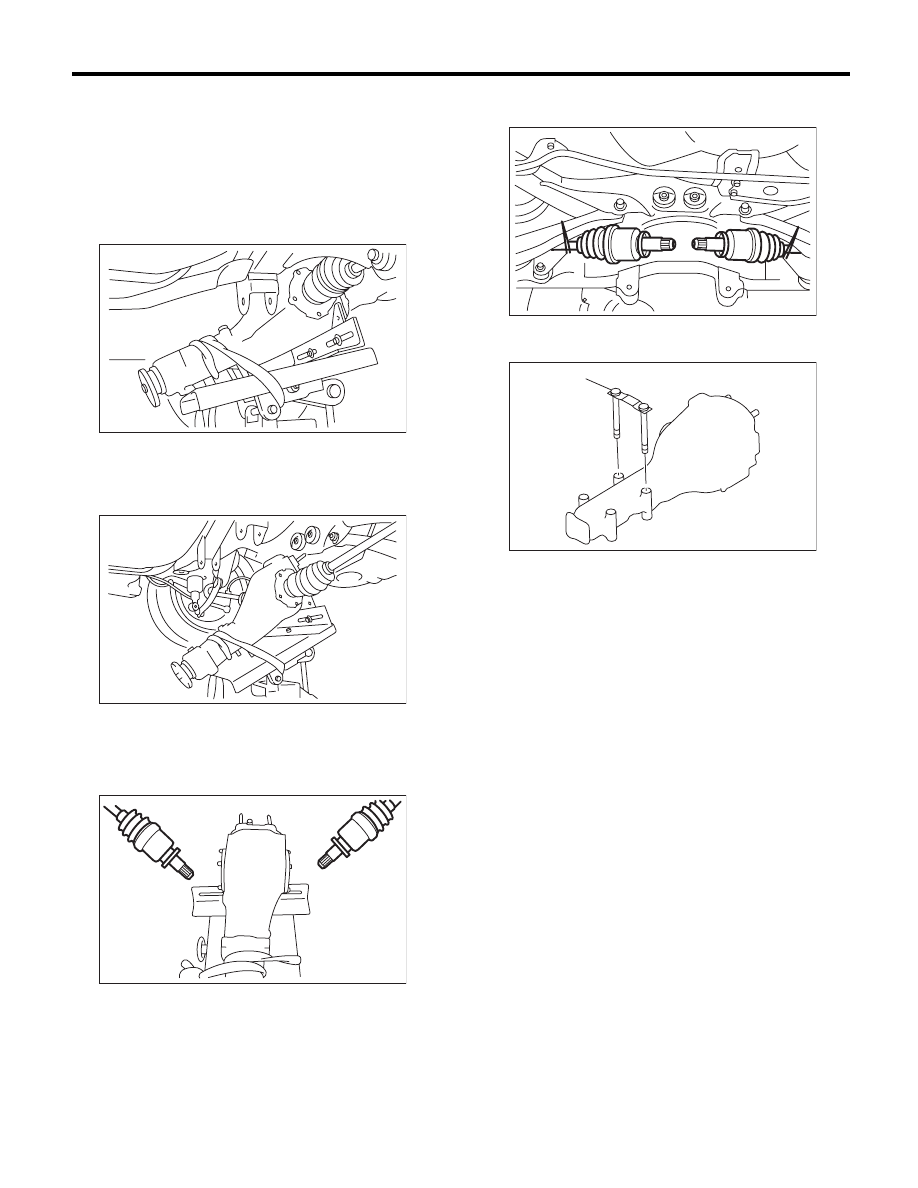
19) Remove the self-lock nuts which hold the rear
differential to rear crossmember.
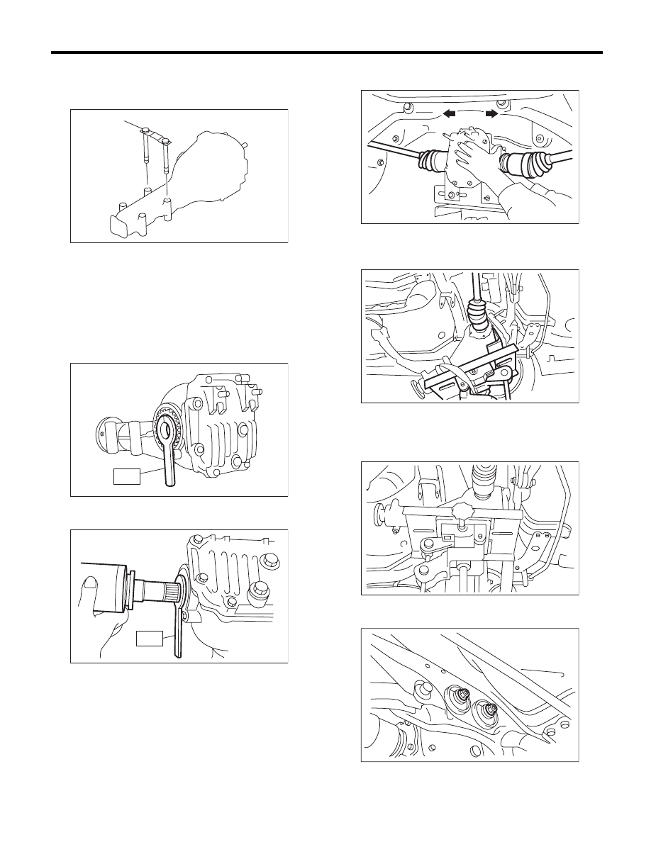
20) Remove the rear differential stud bolt from rear
crossmember bushing.
NOTE:
When removing the stud bolt, carefully adjust the
angle and location of transmission jack and jack
stand, if necessary
21) Lower the transmission jack stand after remov-
ing the rear differential stud bolt from the rear
crossmember. Rear drive shaft should not come
into contact with the lateral link bolt.
22) Pull out the axle shaft from rear differential.
NOTE:
If it is difficult to remove the axle shaft from rear dif-
ferential, remove it using tire lever.
23) Lower the transmission jack.
24) Secure the rear drive shaft to lateral link using
wire.
25) Remove the rear differential member plate from
rear differential.
DI-00400
DI-00392
DI-00276
(A) Rear differential member plate
DI-00277
DI-00359
(A)
DI-58
Rear Differential (VA-type)
DIFFERENTIALS
B: INSTALLATION
1) Insert the rear differential member plate into the
rear differential.
2) Set the rear differential to transmission jack.
NOTE:
Secure the rear differential to transmission jack us-
ing band.
3) Attach the ST to rear differential.
ST
28099PA090
OIL SEAL PROTECTOR
4) Insert the spline shaft until the spline portion
comes inside the side oil seal.
5) Remove ST from rear differential.
6) Push the rear differential to insert the axle shaft
into rear differential.
7) Adjust the transmission jack, if necessary, and
insert the rear differential stud bolt into rear cross-
member bushing properly.
8) After inserting the rear differential stud bolt into
the rear crossmember bushing, lift up the transmis-
sion jack and align the rear differential to its attach-
ment position.
9) Tighten a new self-locking nut temporarily to rear
crossmember.
(A) Rear differential member plate
DI-00359
(A)
DI-00300
ST
DI-00289
ST
DI-00281
DI-00393
DI-00283
DI-00269
DI-59
Rear Differential (VA-type)
DIFFERENTIALS
10) Remove the band from rear differential. Lift up
the rear differential until the rear differential is sep-
arated from the transmission jack.
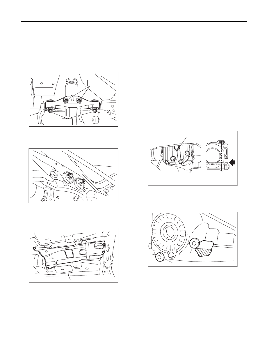
11) Install the rear differential front member with a
new self-locking nut.
Tightening torque:
T1: 50 N·m (5.1 kgf-m, 36.9 ft-lb)
T2: 110 N·m (11.2 kgf-m, 81.1 ft-lb)
12) Tighten the self-locking nut.
Tightening torque:
70 N·m (7.1 kgf-m, 51.6 ft-lb)
13) Lower the transmission jack.
14) Install the propeller shaft. <Ref. to DS-11, IN-
STALLATION, Propeller Shaft.>
15) Install the heat shield cover.
16) Install the rear exhaust pipe and muffler.
• 2.5 L SOHC non-turbo model
<Ref. to EX(H4SO)-8, INSTALLATION, Rear Ex-
haust Pipe.> <Ref. to EX(H4SO)-10, INSTALLA-
TION, Muffler.>
• 2.5 L DOHC turbo model
<Ref. to EX(H4DOTC)-13, INSTALLATION, Rear
Exhaust Pipe.> <Ref. to EX(H4DOTC)-14, IN-
STALLATION, Muffler.>
• 3.0 L DOHC non-turbo model
<Ref. to EX(H6DO)-8, INSTALLATION, Rear Ex-
haust Pipe.> <Ref. to EX(H6DO)-9, INSTALLA-
TION, Muffler.>
17) After installing the rear differential carrier to the
vehicle, remove the filler plug, and refill with gear oil
up to the lower lip of the plug hole.
Oil capacity:
0.8
2
(0.8 US qt, 0.7 Imp qt)
• VA1-type
• VA2-type
DI-00395
T1
T2
DI-00269
AT-01331
(A) Filler plug
(B) Oil drain plug
(A) Filler plug
(B) Oil drain plug
DI-00528
(A)
(B)
(B)
DI-00355
(A)
DI-60
Rear Differential (VA-type)
DIFFERENTIALS
18) Tighten the filler plug.
NOTE:
For VA-type, use a new gasket.
Tightening torque:
VA1-type:
34 N·m (3.5 kgf-m, 25.1 ft-lb)
VA2-type:
50 N·m (5.1 kgf-m, 36.9 ft-lb)
19) Hereafter, install in the reverse order of remov-
al.
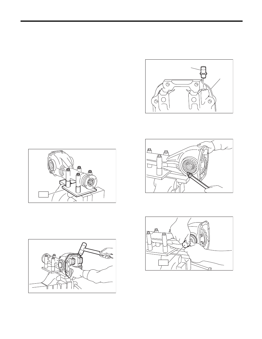
C: DISASSEMBLY
1. VA1-TYPE
To detect the real cause of trouble, inspect the fol-
lowing items before disassembling.
• Tooth contact and backlash between hypoid
driven gear and drive pinion
• Hypoid driven gear runout on its back surface
• Total preload of drive pinion
1) Set the ST on vise and install the differential as-
sembly to ST.
ST
398217700
ATTACHMENT SET
2) Remove the oil drain plug and filler plug, and
drain the gear oil.
3) Remove the mounting bolts, and remove the
rear cover.
NOTE:
Remove by tapping with a plastic hammer.
4) Remove the air breather cap.
NOTE:
• Do not attempt to replace the air breather cap un-
less necessary.
• Whenever the air breather cap is removed, re-
place it with a new part.
5) Remove the lock plate RH and LH.
6) Remove the side retainer RH and LH with the
ST.
ST
18630AA010
WRENCH COMPL
RETAINER
ST
DI-00129
DI-00130
(A) Air breather cap
(B) Rear cover
DI-00561
(A)
(B)
DI-00132
DI-00133
ST
Нет комментариевНе стесняйтесь поделиться с нами вашим ценным мнением.
Текст