Subaru Legacy IV (2008 year). Service manual — part 24
PM-36
Front & Rear Differential Gear Oil
PERIODIC MAINTENANCE SERVICES
15.Front & Rear Differential Gear
Oil
A: REPLACEMENT
1. FRONT DIFFERENTIAL (MT MODEL)
Front differential gear oil of MT model lubricates the
transmission and differential together. Refer to
“Transmission Oil” for replacement procedure.
<Ref. to PM-32, Transmission Gear Oil.>
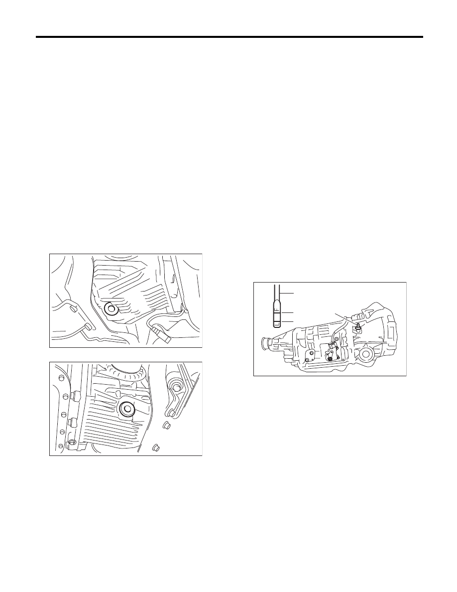
2. FRONT DIFFERENTIAL (AT MODEL)
1) Drain the differential gear oil by removing drain
plug using TORX
®
bit T70.
CAUTION:
If the front differential gear oil is spilt over ex-
haust pipe, wipe it off with cloth to avoid emit-
ting smoke or causing a fire.
NOTE:
• Before starting work, cool off the differential gear
oil well.
• 4AT model
• 5AT model
2) Replace the gasket with new part, and then tight-
en the drain plug to specified torque.
Tightening torque:
• 4AT model
Copper gasket
70 N·m (7.1 kgf-m, 51.6 ft-lb)
Aluminum gasket
44 N·m (4.5 kgf-m, 32.5 ft-lb)
• 5AT model
Copper gasket
70 N·m (7.1 kgf-m, 51.6 ft-lb)
3) Fill differential gear oil through the oil level
gauge hole up to the upper point of level gauge.
Recommended gear oil:
Refer to RM section. <Ref. to RM-2, LUBRI-
CANTS, RECOMMENDED MATERIALS, Rec-
ommended Materials.>
NOTE:
Each oil manufacturer has its base oil and addi-
tives. Thus, do not mix two or more brands.
Gear oil capacity:
4AT model
1.1 — 1.3
2
(1.2 — 1.4 US qt, 1.0 — 1.1 Imp qt)
PM-00169
PM-00170
(A) Oil level gauge
(B) Upper level
(C) Lower level
AT-04840
(B)
(C)
(A)
(A)
PM-37
Front & Rear Differential Gear Oil
PERIODIC MAINTENANCE SERVICES
5AT model
1.3 — 1.5
2
(1.4 — 1.6 US qt, 1.1 — 1.3 Imp qt)
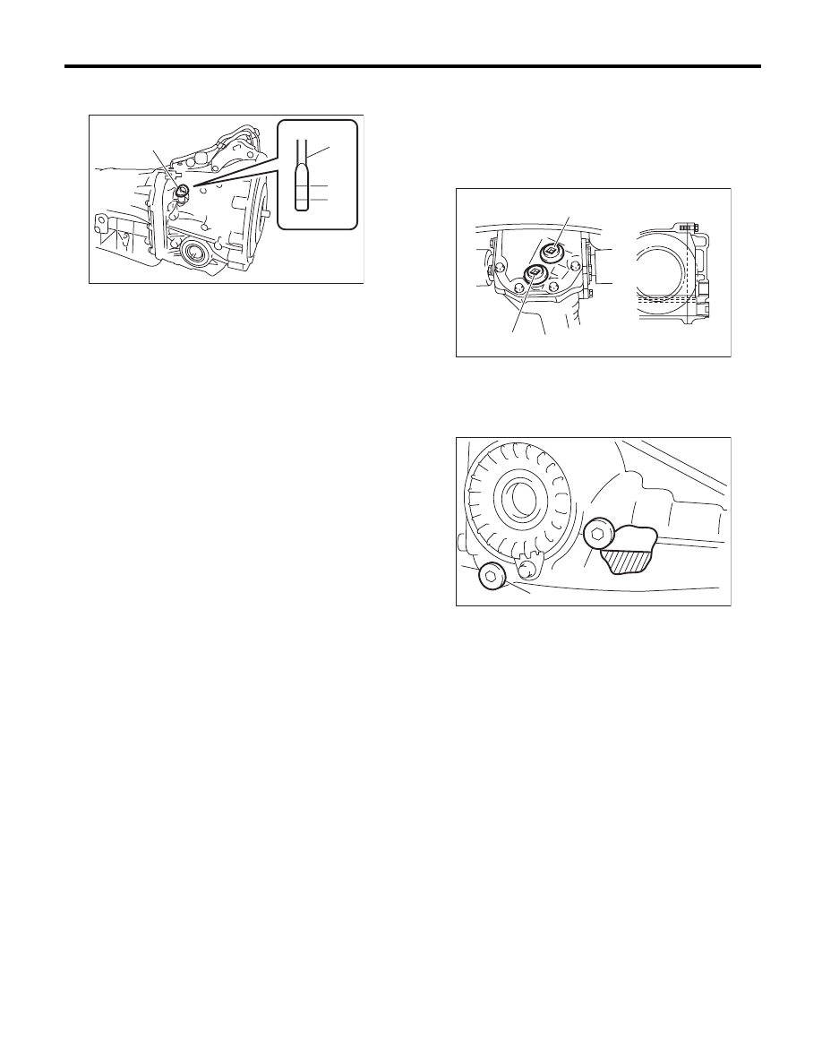
3. REAR DIFFERENTIAL
1) Drain the oil by removing drain plug.
2) Remove the filler plug for quick draining oil.
3) Install the drain plug after draining oil.
NOTE:
• Apply liquid gasket to the drain plug threads for
T-type (except for turbo 6MT model).
• Use a new gasket for VA-type and T-type (turbo
6MT model).
Liquid gasket:
THREE BOND 1105 (Part No. 004403010)
Tightening torque:
T-type (except for turbo 6MT model)
49.0 N·m (5.0 kgf-m, 36.2 ft-lb)
T-type (turbo 6MT model)
60 N·m (6.1 kgf-m, 44.3 ft-lb)
VA1-type
34 N·m (3.5 kgf-m, 25.1 ft-lb)
VA2-type
50 N·m (5.1 kgf-m, 36.9 ft-lb)
4) Pour oil to the bottom end of filler plug hole.
Recommended gear oil:
Refer to RM section. <Ref. to RM-2, LUBRI-
CANTS, RECOMMENDED MATERIALS, Rec-
ommended Materials.>
• Except for VA2-type
• VA2-type
Oil capacity:
Except for turbo 6MT model
0.8
2
(0.8 US qt, 0.7 Imp qt)
Turbo 6MT model
1.0
2
(1.1 US qt, 0.9 Imp qt)
NOTE:
Each oil manufacturer has its base oil and addi-
tives. Thus, do not mix two or more brands.
(A) Oil level gauge
(B) Upper level
(C) Lower level
PI-00184
(A)
(C)
(B)
(A)
F
L
(A) Filler plug
(B) Drain plug
(A) Filler plug
(B) Drain plug
PM-00037
(A)
(B)
(B)
DI-00355
(A)
PM-38
Front & Rear Differential Gear Oil
PERIODIC MAINTENANCE SERVICES
5) Install the filler plug.
NOTE:
• Apply liquid gasket to the drain plug threads for
T-type (except for turbo 6MT model).
• Use a new gasket for VA-type and T-type (turbo
6MT model).
Liquid gasket:
THREE BOND 1105 (Part No. 004403010)
Tightening torque:
T-type (except for turbo 6MT model)
49.0 N·m (5.0 kgf-m, 36.2 ft-lb)
T-type (turbo 6MT model)
60 N·m (6.1 kgf-m, 44.3 ft-lb)
VA1-type
34 N·m (3.5 kgf-m, 25.3 ft-lb)
VA2-type
50 N·m (5.1 kgf-m, 36.9 ft-lb)
PM-39
Brake Line
PERIODIC MAINTENANCE SERVICES
16.Brake Line
A: INSPECTION
1. BRAKE LINE
1) Check for scratches, swelling, corrosion, traces
of fluid leakage on the brake hoses or pipe joints.
2) Check the possibility of adjacent parts interfering
with brake pipes/hoses during driving, and loose
connections/clamps.
3) Check any trace of fluid leakage, scratches, etc.
on master cylinder, wheel cylinder and pressure
control valve.
NOTE:
• When the brake fluid level in the reservoir tank is
lower than specified limit, the brake warning light
on the combination meter will illuminate.
• Visually check the brake hose for damage. (Use
a mirror where it is difficult to see)
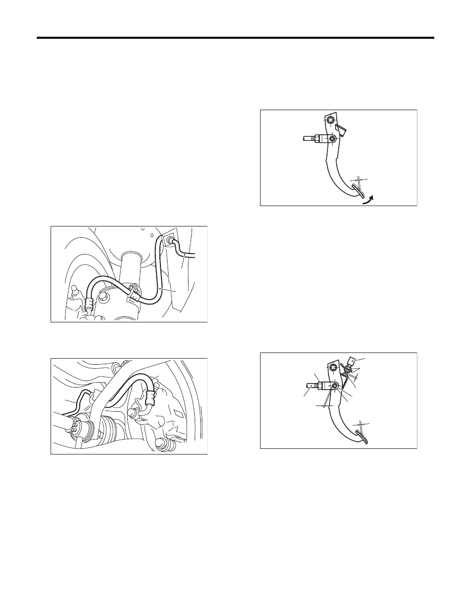
2. SERVICE BRAKE
1) Check the free play of brake pedal by pulling up
the pedal with a force of 10 N (1 kgf, 2 lb) or less.
Brake pedal free play (Pulling up direction of
pedal)
0.5 — 2.0 mm (0.02 — 0.08 in)
2) If the free play is out of specifications above, ad-
just the brake pedal as follows.
(1) Make sure the engine is off. (No vacuum is
applied to brake booster.)
(2) There should be play between brake boost-
er clevis and pin at brake pedal installing por-
tion. [Pulling up the brake pedal pad with a force
of 10 N (1 kgf, 2 lb) or less to a stroke of 0.5 to
2.0 mm (0.02 to 0.08 in).]
(3) If there is no free play between clevis pin
and clevis, turn brake switch adjusting nut until
the clearance between stopper and screw of
brake switch becomes 0.3 mm (0.012 in).
(1) Front brake hose
(2) Front brake pipe
(1) Rear brake pipe
(2) Rear brake hose
PM-00171
(2)
(1)
(2)
(1)
PM-00172
(A) Pedal free play
(A) Brake switch
(B) Adjusting nut
(C) 0.3 mm (0.012 in)
(D) Stopper
(E) Clevis pin
(F) Clevis
(G) Pedal free play
(H) Lock nut
(I) Brake booster operating rod
(J) Play at pin
PM-00185
(A)
PM-00186
(B)
(G)
(H)
(I)
(J)
(C)
(D)
(E)
(F)
(A)
Нет комментариевНе стесняйтесь поделиться с нами вашим ценным мнением.
Текст