Subaru Legacy IV (2008 year). Service manual — part 231
FU(H4DOTC)-27
Intake Manifold
FUEL INJECTION (FUEL SYSTEMS)
D: ASSEMBLY
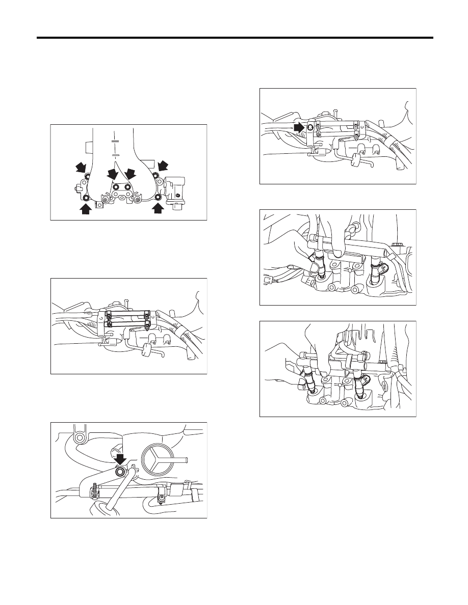
1) Install the tumble generator valve assembly onto
intake manifold.
NOTE:
Use new O-rings.
Tightening torque:
8.3 N·m (0.8 kgf-m, 6.1 ft-lb)
2) Install the fuel injector pipe.
3) Connect fuel hoses to fuel injector pipes on both
sides, and secure them with the clamps.
Tightening torque:
1.25 N·m (0.1 kgf-m, 0.9 ft-lb)
4) Tighten the bolts which secure the fuel injector
pipe RH to the lower side of the intake manifold.
Tightening torque:
6.4 N·m (0.7 kgf-m, 4.7 ft-lb)
5) Tighten the bolts which secure fuel injector pipe
onto intake manifold.
Tightening torque:
6.4 N·m (0.7 kgf-m, 4.7 ft-lb)
6) Install the fuel injector.
• RH side
• LH side
FU-03039
FU-03111
FU-03110
FU-03109
FU-03094
FU-03091
FU(H4DOTC)-28
Intake Manifold
FUEL INJECTION (FUEL SYSTEMS)
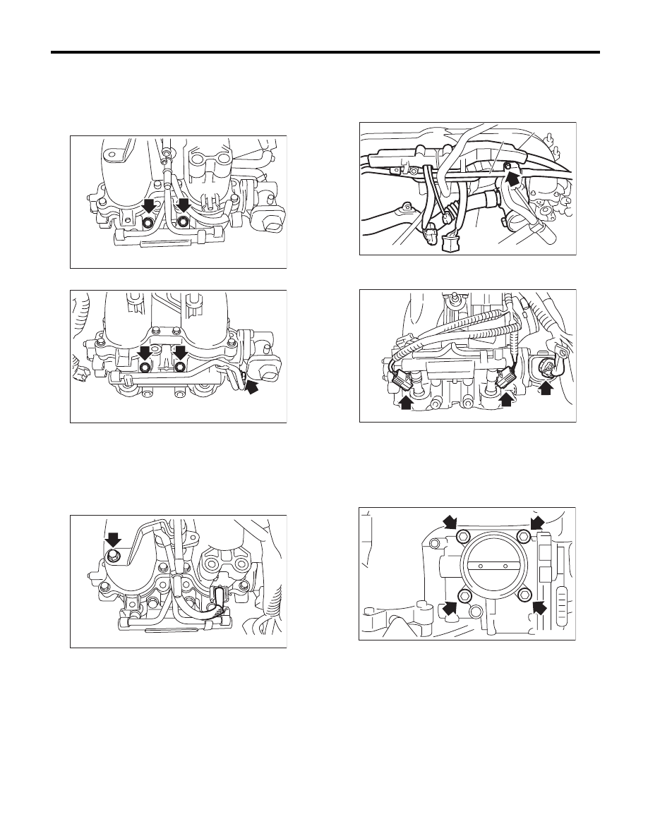
7) Tighten the bolts which secure fuel injector pipe
onto intake manifold.
Tightening torque:
19 N·m (1.9 kgf-m, 14.0 ft-lb)
• LH side
• RH side
8) Tighten the bolt which holds the fuel injector pipe
LH to the front side of the intake manifold, and con-
nect the pressure regulator vacuum hose to the in-
take manifold.
Tightening torque:
6.4 N·m (0.7 kgf-m, 4.7 ft-lb)
9) Install PCV pipe (A), harness assembly (B) and
intake duct (C) to the intake manifold.
Tightening torque:
6.5 N·m (0.7 kgf-m, 4.8 ft-lb)
10) Connect the connector to the fuel injector and
the tumble generator valve assembly.
11) Install the throttle body to the intake manifold.
NOTE:
Use new O-rings.
Tightening torque:
8 N·m (0.8 kgf-m, 5.9 ft-lb)
FU-03090
FU-03089
FU-04031
FU-03033
(C)
(A)
(B)
FU-03088
FU-03815
FU(H4DOTC)-29
Intake Manifold
FUEL INJECTION (FUEL SYSTEMS)
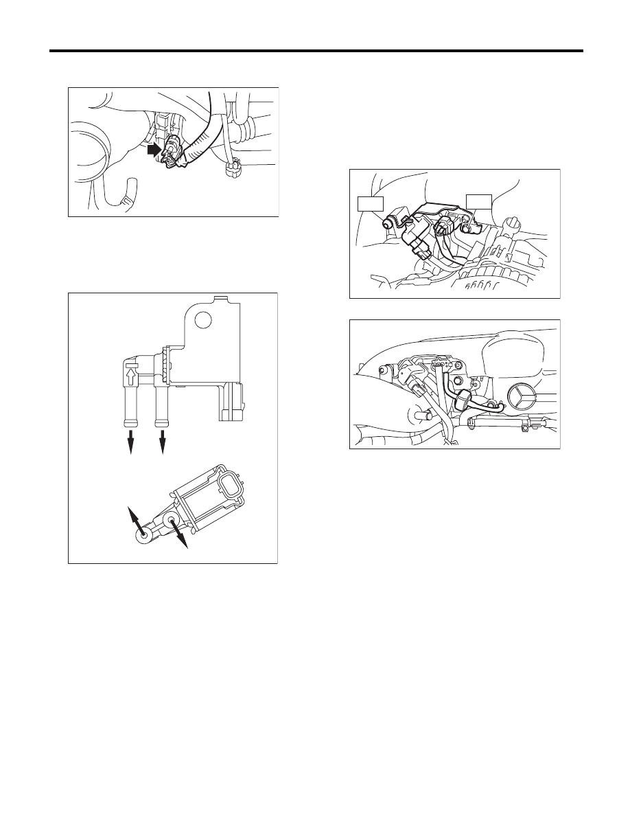
12) Connect the connector to the throttle position
sensor.
13) Connect the evaporation hose to the purge
control solenoid valve 2.
NOTE:
Connect the evaporation hose as shown in the fig-
ure.
14) Connect the connectors to the wastegate con-
trol solenoid valve, manifold absolute pressure
sensor and purge control solenoid valve 2, and in-
stall the solenoid valve bracket assembly to the in-
take manifold.
Tightening torque:
T1: 17 N·m (1.7 kgf-m, 12.5 ft-lb)
T2: 19 N·m (1.9 kgf-m, 14.0 ft-lb)
15) Connect the filter assembly.
(A) Purge control solenoid valve 1
(B) Purge control solenoid valve 2
(a) To intake manifold
(b) To intake duct
(c) To fuel pipe
FU-03463
EC-02201
(A)
(B)
(b)
(c)
(c)
(a)
EC-02252
T2
T1
FU-03030
FU(H4DOTC)-30
Intake Manifold
FUEL INJECTION (FUEL SYSTEMS)
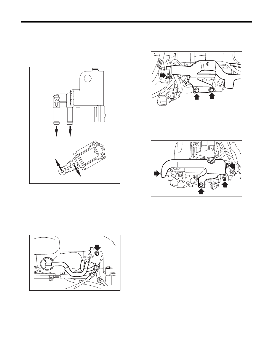
16) Connect the evaporation hose and the connec-
tor to the purge control solenoid valve 1, and install
the purge control solenoid valve 1 to the intake
manifold.
NOTE:
Connect the evaporation hose as shown in the fig-
ure.
Tightening torque:
6.4 N·m (0.7 kgf-m, 4.7 ft-lb)
17) Install the fuel pipe protector RH to the intake
manifold.
Tightening torque:
19 N·m (1.9 kgf-m, 14.0 ft-lb)
18) Install the fuel pipe protector LH to the intake
manifold, and install the engine ground terminal to
the fuel pipe protector LH.
Tightening torque:
19 N·m (1.9 kgf-m, 14.0 ft-lb)
E: INSPECTION
Make sure that the fuel pipe and fuel hose are not
cracked and that the connections are tight.
(A) Purge control solenoid valve 1
(B) Purge control solenoid valve 2
(a) To intake manifold
(b) To intake duct
(c) To fuel pipe
EC-02201
(A)
(B)
(b)
(c)
(c)
(a)
FU-04030
FU-03087
FU-03086
Нет комментариевНе стесняйтесь поделиться с нами вашим ценным мнением.
Текст