Subaru Legacy IV (2008 year). Service manual — part 157
EN(H4SO)(diag)-231
Diagnostic Procedure with Diagnostic Trouble Code (DTC)
ENGINE (DIAGNOSTICS)
CA:DTC P0607 THROTTLE CONTROL SYSTEM CIRCUIT RANGE/PERFORMANCE
DTC DETECTING CONDITION:
• Immediately at fault recognition
• GENERAL DESCRIPTION <Ref. to GD(H4SO)-147, DTC P0607 THROTTLE CONTROL SYSTEM CIR-
CUIT RANGE/PERFORMANCE, Diagnostic Trouble Code (DTC) Detecting Criteria.>
TROUBLE SYMPTOM:
• Improper idling
• Poor driving performance
CAUTION:
After repair or replacement of faulty parts, perform Clear Memory Mode <Ref. to EN(H4SO)(diag)-50,
OPERATION, Clear Memory Mode.>, and Inspection Mode <Ref. to EN(H4SO)(diag)-41, PROCEDURE,
Inspection Mode.>.
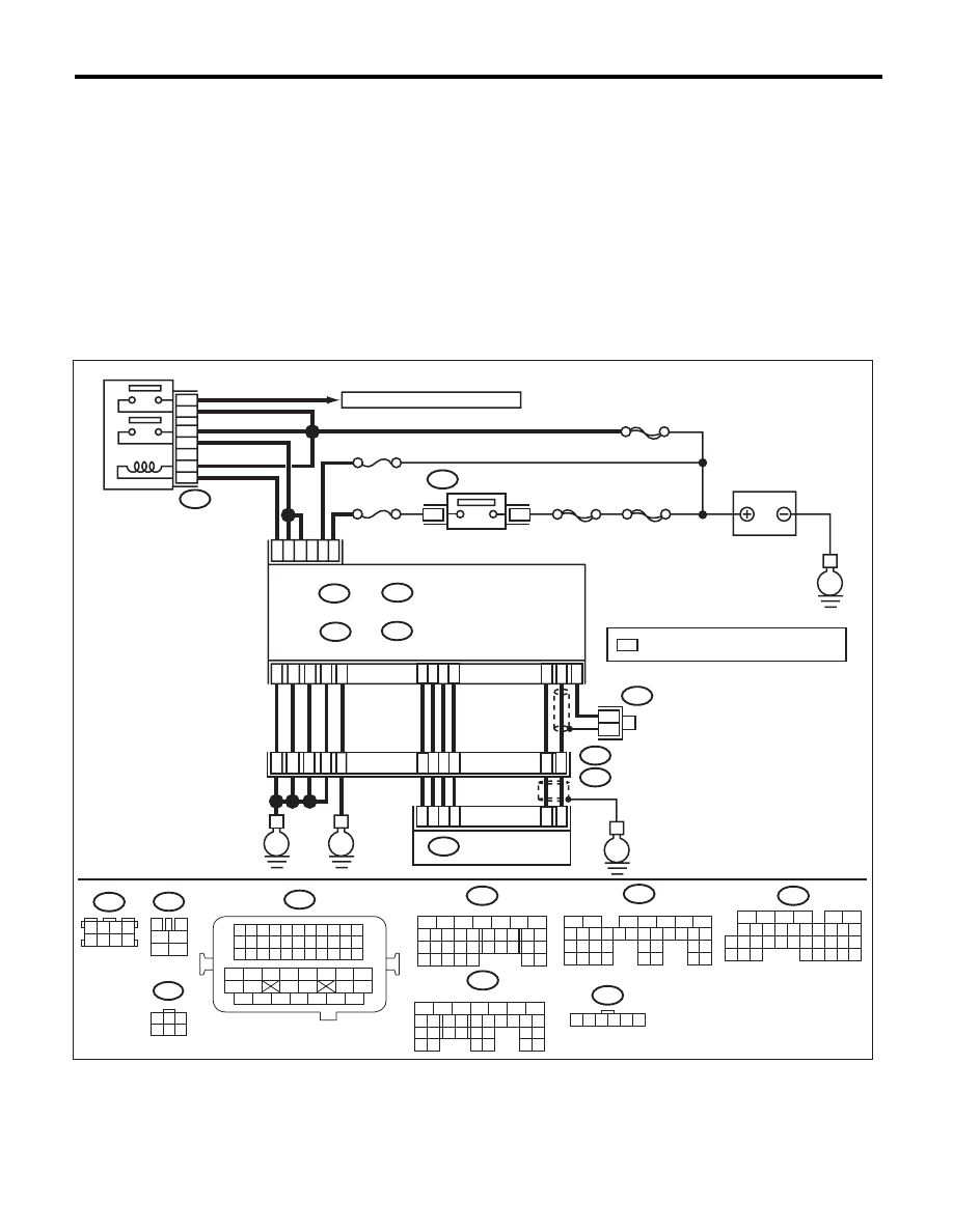
WIRING DIAGRAM:
EN-06842
SBF-6
MAIN SBF
SBF-7
B72
B2
A7
C24
A5
D2
D1
D3
D7
B5
B27
No. 12
B47
E2
B21
2
1
4
6
5
3
E
3
4
B134
B135
A:
D: B137
B:
36
35
52
37
34
3
4
1
2
5
6
B47
No. 13
B134
5
6
7
8
2
1
9
4
3
10
24
22 23
25
11 12 13 14 15
26 27
28
16 17
18 19 20 21
33 34
29
32
30 31
B135
5
6
7
8
2
1
9
4
3
10
24
22 23
25
11 12 13 14 15
26 27
28
16 17 18 19
20 21
29 30 31
32 33
34 35
B21
1 2 3 4
12 13 14 15
5 6 7 8
16 17 18 19
9 10 11
20 21 22
23 24 25 26 27 28 29 30 31 32 33
35
34
37
36
39
38
41
40
43
42
44
45
47
46
49
48
51
50
53
52
54
B72
1
3
4 5 6
2
A:
B:
MAIN RELAY
ECM
TO IGNITION COIL & IGNITOR ASSY
BATTERY
IGNITION
SWITCH
E
E
*
*
E
C: B136
B122
E57
: TERMINAL No. OPTIONAL ARRANGEMENT
A19
D4
D5
A29
A28
A18
C6
20
39
38
19
5
1
2
3
18
17
4
6
ELECTRONIC
THROTTLE CONTROL
B122
3 4
5 6
1 2
7 8
B136
C:
16
10 11 12 13 14 15
25
24
30
9
8
7
17 18 19 20
28
21 22 23
29
32
31
1
2
3
4
5
6
27
26
33 34 35
*
B137
5
6
7
8
2
1
9
4
3
10
22 23
11 12 13 14 15
24 25
26
16 17
18 19 20 21
27
28 29
30 31
D:
E57
1 2 3 4 5 6

EN(H4SO)(diag)-232
Diagnostic Procedure with Diagnostic Trouble Code (DTC)
ENGINE (DIAGNOSTICS)
CB:DTC P0638 THROTTLE ACTUATOR CONTROL RANGE/PERFORMANCE
(BANK 1)
NOTE:
For the diagnostic procedure, refer to DTC P2101. <Ref. to EN(H4SO)(diag)-276, DTC P2101 THROTTLE
ACTUATOR CONTROL MOTOR CIRCUIT RANGE/PERFORMANCE, Diagnostic Procedure with Diagnos-
tic Trouble Code (DTC).>
CC:DTC P0700 TRANSMISSION CONTROL SYSTEM (MIL REQUEST)
NOTE:
For the diagnostic procedure, refer to AT section. <Ref. to 4AT(diag)-2, Basic Diagnostic Procedure.>
Step
Check
Yes
No
1
CHECK INPUT VOLTAGE OF ECM.
1) Turn the ignition switch to ON.
2) Measure the voltage between ECM and
chassis ground.
Connector & terminal
(B134) No. 7 (+) — Chassis ground (–):
(B135) No. 2 (+) — Chassis ground (–):
Is the voltage 10 — 13 V?
Go to step 2.
Repair the open or
ground short circuit
of power supply
circuit.
2
CHECK INPUT VOLTAGE OF ECM.
1) Start the engine.
2) Measure the voltage between ECM and
chassis ground.
Connector & terminal
(B134) No. 7 (+) — Chassis ground (–):
(B135) No. 2 (+) — Chassis ground (–):
Is the voltage 13 — 15 V?
Go to step 3.
Repair the open or
ground short circuit
of power supply
circuit.
3
CHECK HARNESS BETWEEN ECM AND
ELECTRONIC THROTTLE CONTROL.
1) Turn the ignition switch to OFF.
2) Disconnect the connectors from ECM and
electronic throttle control.
3) Measure the resistance of harness between
ECM and electronic throttle control connector.
Connector & terminal
(B134) No. 19 — (E57) No. 5:
(B134) No. 29 — (E57) No. 3:
Is the resistance less than 1
:? Go to step 4.
Repair the harness
and connector.
NOTE:
In this case, repair
the following item:
• Open circuit in
harness between
ECM and electron-
ic throttle control
connector
• Poor contact of
coupling connector
4
CHECK ECM GROUND HARNESS.
Measure the voltage between ECM and chassis
ground.
Connector & terminal
(B134) No. 5 (+) — Chassis ground (–):
(B137) No. 1 (+) — Chassis ground (–):
(B137) No. 2 (+) — Chassis ground (–):
(B137) No. 3 (+) — Chassis ground (–):
(B137) No. 7 (+) — Chassis ground (–):
Is the voltage less than 1 V?
Repair the poor
contact of ECM
connector.
Repair the follow-
ing item.
• Open circuit of
ground circuit
• Retightening of
engine ground ter-
minals
• Poor contact of
coupling connector
EN(H4SO)(diag)-233
Diagnostic Procedure with Diagnostic Trouble Code (DTC)
ENGINE (DIAGNOSTICS)
CD:DTC P0851 PARK/NEUTRAL SWITCH INPUT CIRCUIT LOW (AT MODEL)
DTC DETECTING CONDITION:
• Two consecutive driving cycles with fault
• GENERAL DESCRIPTION <Ref. to GD(H4SO)-152, DTC P0851 PARK/NEUTRAL SWITCH INPUT CIR-
CUIT LOW (AT MODEL), Diagnostic Trouble Code (DTC) Detecting Criteria.>
TROUBLE SYMPTOM:
Improper idling
CAUTION:
After repair or replacement of faulty parts, perform Clear Memory Mode <Ref. to EN(H4SO)(diag)-50,
OPERATION, Clear Memory Mode.>, and Inspection Mode <Ref. to EN(H4SO)(diag)-41, PROCEDURE,
Inspection Mode.>.
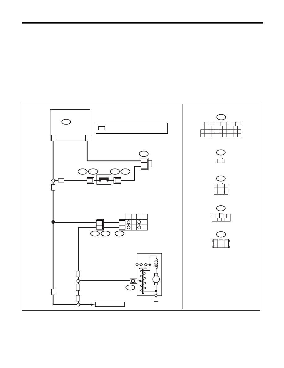
WIRING DIAGRAM:
EN-06642
B12
T3
B14
T7
INHIBITOR
SWITCH
NEUTRAL
POSITION
SWITCH
STARTER MOTOR
(MAGNET)
P
R
N
D
6
9
12
11
B136
ECM
31
6
B12
B25
T7
1 2 3 4
5 6 7 8
9 10 11 12
B136
1
B25
T2
T2
B25
2
MT
AT
AT
AT
MT
MT
M
2
1
C:
C:
B122
*
*
: TERMINAL No. OPTIONAL ARRANGEMENT
*
16
10 11 12 13 14 15
25
24
30
9
8
7
17 18 19 20
28
21 22 23
29
32
31
1
2
3
4
5
6
27
26
33 34 35
B122
3 4
5 6
1 2
7 8
TO STARTER RELAY
1 2 3 4 5
7
6
9
8

EN(H4SO)(diag)-234
Diagnostic Procedure with Diagnostic Trouble Code (DTC)
ENGINE (DIAGNOSTICS)
Step
Check
Yes
No
1
CHECK SELECT CABLE.
Are there any faults in the select
cable?
Repair or adjust
the select cable.
<Ref. to CS-28,
Select Cable.>
Go to step 2.
2
CHECK INPUT SIGNAL OF ECM.
1) Turn the ignition switch to ON.
2) Place the select lever in other than “P” range
and “N” range.
3) Measure the voltage between ECM and
chassis ground.
Connector & terminal
(B136) No. 31 (+) — Chassis ground (–):
Is the voltage 10 V or more?
Repair the poor
contact of ECM
connector.
Go to step 3.
3
CHECK HARNESS BETWEEN ECM AND
TRANSMISSION HARNESS CONNECTOR.
1) Turn the ignition switch to OFF.
2) Disconnect the connectors from ECM and
transmission harness connector (T3).
3) Measure the resistance between ECM and
chassis ground.
Connector & terminal
(B136) No. 31 — Chassis ground:
Is the resistance 1 M
: or
more?
Go to step 4.
Repair the ground
short circuit of har-
ness between
ECM and transmis-
sion harness con-
nector.
4
CHECK TRANSMISSION HARNESS CON-
NECTOR.
1) Disconnect the connector from inhibitor
switch.
2) Measure the resistance between the trans-
mission harness connector and engine ground.
Connector & terminal
(T3) No. 11 — Engine ground:
Is the resistance 1 M
: or
more?
Replace the inhibi-
tor switch. <Ref. to
4AT-46, Inhibitor
Switch.>
Repair the ground
short circuit of har-
ness between
transmission har-
ness connector
and inhibitor switch
connector.
Нет комментариевНе стесняйтесь поделиться с нами вашим ценным мнением.
Текст