Subaru Legacy IV (2008 year). Service manual — part 584

EN(H6DO)(diag)-309
Diagnostic Procedure with Diagnostic Trouble Code (DTC)
ENGINE (DIAGNOSTICS)
Step
Check
Yes
No
1
CHECK HARNESS BETWEEN ECM AND OIL
FLOW CONTROL SOLENOID VALVE.
1) Turn the ignition switch to OFF.
2) Disconnect the connectors from ECM and
oil flow control solenoid valve.
3) Measure the resistance of harness between
ECM and oil flow control solenoid valve.
Connector & terminal
(B137) No. 15 — (E68) No. 1:
(B137) No. 14 — (E68) No. 2:
Is the resistance less than 1
:? Go to step 2.
Repair the harness
and connector.
NOTE:
In this case, repair
the following item:
• Open circuit of
the harness be-
tween the ECM
and oil flow control
solenoid valve
connector
• Poor contact of
coupling connector
2
CHECK HARNESS BETWEEN ECM AND OIL
FLOW CONTROL SOLENOID VALVE.
Measure the resistance between ECM and
chassis ground.
Connector & terminal
(B137) No. 15 — Chassis ground:
(B137) No. 14 — Chassis ground:
Is the resistance 1 M
: or
more?
Go to step 3.
Repair the short
circuit to ground in
harness between
ECM and oil flow
control solenoid
valve connector.
3
CHECK OIL FLOW CONTROL SOLENOID
VALVE.
Measure the resistance between oil flow control
solenoid valve terminals.
Terminals
No. 1 — No. 2:
Is the resistance between 6 —
12
:?
Repair the poor
contact of ECM
and oil flow control
solenoid valve con-
nector.
Replace the oil
flow control sole-
noid valve. <Ref. to
ME(H6DO)-55,
Camshaft.>
EN(H6DO)(diag)-310
Diagnostic Procedure with Diagnostic Trouble Code (DTC)
ENGINE (DIAGNOSTICS)
DW:DTC P2093 INTAKE CAMSHAFT POSITION ACTUATOR CONTROL CIRCUIT
HIGH (BANK 2)
DTC DETECTING CONDITION:
• Immediately at fault recognition
• GENERAL DESCRIPTION <Ref. to GD(H6DO)-186, DTC P2093 INTAKE CAMSHAFT POSITION ACTU-
ATOR CONTROL CIRCUIT HIGH (BANK 2), Diagnostic Trouble Code (DTC) Detecting Criteria.>
TROUBLE SYMPTOM:
Improper idling
CAUTION:
After repair or replacement of faulty parts, perform Clear Memory Mode <Ref. to EN(H6DO)(diag)-52,
OPERATION, Clear Memory Mode.>, and Inspection Mode <Ref. to EN(H6DO)(diag)-44, PROCEDURE,
Inspection Mode.>.
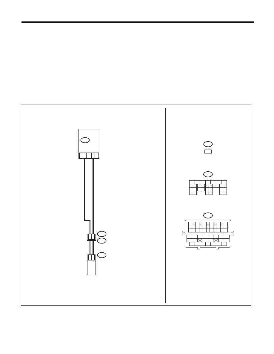
WIRING DIAGRAM:
EN-06882
B21
E2
B137
E68
14
2
1
28
27
15
ECM
OIL FLOW CONTROL
SOLENOID VALVE LH
E68
1 2
B137
5
6
7
8
2
1
9
4
3
10
22 23
11 12 13 14 15
24 25
26
16 17
18 19 20 21
27
28 29
30 31
B21
1 2 3 4 5 6 7 8 9 10 11
12 13 14 15 16 17 18 19 20 21 22
23 24 25 26 27 28 29 30 31 32 33
34
35
42
43
36
37
38
39
48
49
50
51
52
53
54
40
41
44
45
46
47

EN(H6DO)(diag)-311
Diagnostic Procedure with Diagnostic Trouble Code (DTC)
ENGINE (DIAGNOSTICS)
DX:DTC P2096 POST CATALYST FUEL TRIM SYSTEM TOO LEAN (BANK 1)
NOTE:
Refer to DTC P2097 for diagnostic procedure. <Ref. to EN(H6DO)(diag)-312, DTC P2097 POST CATALYST
FUEL TRIM SYSTEM TOO RICH (BANK 1), Diagnostic Procedure with Diagnostic Trouble Code (DTC).>
Step
Check
Yes
No
1
CHECK HARNESS BETWEEN ECM AND OIL
FLOW CONTROL SOLENOID VALVE.
1) Turn the ignition switch to OFF.
2) Disconnect the connectors from ECM and
oil flow control solenoid valve.
3) Measure the voltage between ECM and
chassis ground.
Connector & terminal
(B137) No. 15 (+) — Chassis ground (–):
(B137) No. 14 (+) — Chassis ground (–):
Is the voltage less than 1 V?
Go to step 2.
Repair the short
circuit to power in
harness between
ECM and oil flow
control solenoid
valve connector.
2
CHECK HARNESS BETWEEN ECM AND OIL
FLOW CONTROL SOLENOID VALVE.
Measure the resistance of harness between
ECM and oil flow control solenoid valve connec-
tor.
Connector & terminal
(B137) No. 15 — (E68) No. 1:
(B137) No. 14 — (E68) No. 2:
Is the resistance less than 1
:? Go to step 3.
Repair the harness
and connector.
NOTE:
In this case, repair
the following item:
• Open circuit of
the harness be-
tween the ECM
and oil flow control
solenoid valve
connector
• Poor contact of
coupling connector
3
CHECK OIL FLOW CONTROL SOLENOID
VALVE.
Measure the resistance between oil flow control
solenoid valve terminals.
Terminals
No. 1 — No. 2:
Is the resistance between 6 —
12
:?
Repair the poor
contact of ECM
and oil flow control
solenoid valve con-
nector.
Replace the oil
flow control sole-
noid valve. <Ref. to
ME(H6DO)-55,
Camshaft.>
EN(H6DO)(diag)-312
Diagnostic Procedure with Diagnostic Trouble Code (DTC)
ENGINE (DIAGNOSTICS)
DY:DTC P2097 POST CATALYST FUEL TRIM SYSTEM TOO RICH (BANK 1)
DTC DETECTING CONDITION:
• Two consecutive driving cycles with fault
• GENERAL DESCRIPTION <Ref. to GD(H6DO)-189, DTC P2097 POST CATALYST FUEL TRIM SYS-
TEM TOO RICH (BANK 1), Diagnostic Trouble Code (DTC) Detecting Criteria.>
CAUTION:
After repair or replacement of faulty parts, perform Clear Memory Mode <Ref. to EN(H6DO)(diag)-52,
OPERATION, Clear Memory Mode.>, and Inspection Mode <Ref. to EN(H6DO)(diag)-44, PROCEDURE,
Inspection Mode.>.
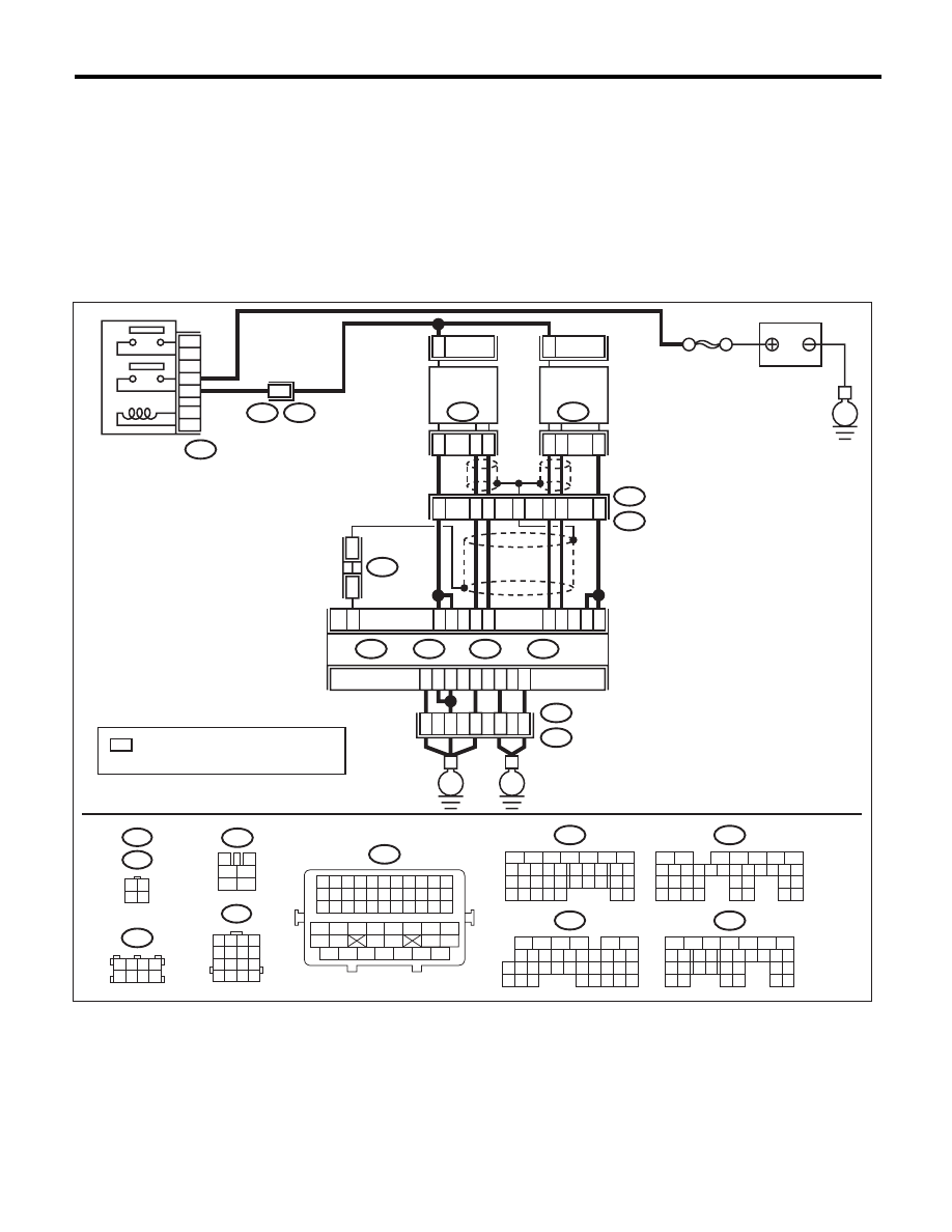
WIRING DIAGRAM:
SBF-5
BATTERY
E
E3
B22
B47
1
2
3
5
4
6
MAIN RELAY
E3
B22
8
: TERMINAL No. OPTIONAL ARRANGEMENT
AMONG 1, 2, 5 AND 6
*
3
4
5
6
1
2
B47
1 2 3 4
5 6 7 8
9 10 11 12
13 14 15 16
B22
3 4
1 2
E47
E24
16
10 11 12 13 14 15
25
24
30
9
8
7
17 18 19 20
28
21 22 23
29
32
31
1
2
3
4
5
6
27
26
33 34 35
B136
C:
5
6
7
8
2
1
9
4
3
10
22 23
11 12 13 14 15
24 25
26
16 17
18 19 20 21
27
28 29
30 31
B137
D:
1 2 3 4
5 6 7 8
B138
5
6
7
8
2
1
9
4
3
10
24
22 23
25
11 12 13 14 15
26 27
28
16 17 18 19
20 21
29 30 31
32 33
34 35
B135
B:
5
6
7
8
2
1
9
4
3
10
24
22 23
25
11 12 13 14 15
26 27
28
16 17
18 19 20 21
33 34
29
32
30 31
B134
A:
B11
2
E24
FRONT
OXYGEN (A/F)
SENSOR LH
3
4
B10
1
B7
B6
C2
C3
B8
4
1
3
B9
ECM
B135
B:
B134
A:
B137
D:
B136
C:
D3
A3
D2
D1
D7
A5
35
34
52
36
37
B21
E2
E
E
EN-06867
B21
1 2 3 4 5 6 7 8 9 10 11
12 13 14 15 16 17 18 19 20 21 22
23 24 25 26 27 28 29 30 31 32 33
34
35
42
43
36
37
38
39
48
49
50
51
52
53
54
40
41
44
45
46
47
2
E47
FRONT
OXYGEN (A/F)
SENSOR RH
5
6
7
4
2
1
3
B138
*
*
B1
Нет комментариевНе стесняйтесь поделиться с нами вашим ценным мнением.
Текст