Subaru Legacy IV (2008 year). Service manual — part 1073
GW-19
Scalp Cap
GLASS/WINDOWS/MIRRORS
7. Scalp Cap
A: REPLACEMENT
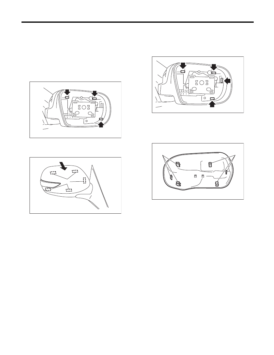
1. MODEL WITH SIDE TURN SIGNAL
LIGHT
1) Remove the outer mirror. <Ref. to GW-21, RE-
PLACEMENT, Outer Mirror.>
2) Press-in the upper side clips (A) from inside of
outer mirror.
3) Pull the scalp cap frontward of outer mirror, re-
move the upper side clips (A), and then remove the
scalp cap.
4) Install the scalp cap securely.
CAUTION:
Do not remove the scalp cap forcibly. The lower
hooks may be damaged.
2. MODEL WITHOUT SIDE TURN SIGNAL
LIGHT
1) Remove the mirror. <Ref. to GW-21, REPLACE-
MENT, Outer Mirror.>
2) Press-in the clips (A) from inside of outer mirror.
3) Pull the scalp cap towards the front of the outer
mirror, then remove the scalp cap.
4) Align clip (A) on the reverse side of the scalp cap
and the clip attachment hole of the outer mirror,
and push the scalp cap in.
5) Install the scalp cap securely.
GW-00568
(A)
(A)
(A)
GW-00569
(A)
GW-00389
(A)
(A)
(A)
(A)
(A)
(A)
GW-00390
GW-20
Outer Mirror Assembly
GLASS/WINDOWS/MIRRORS
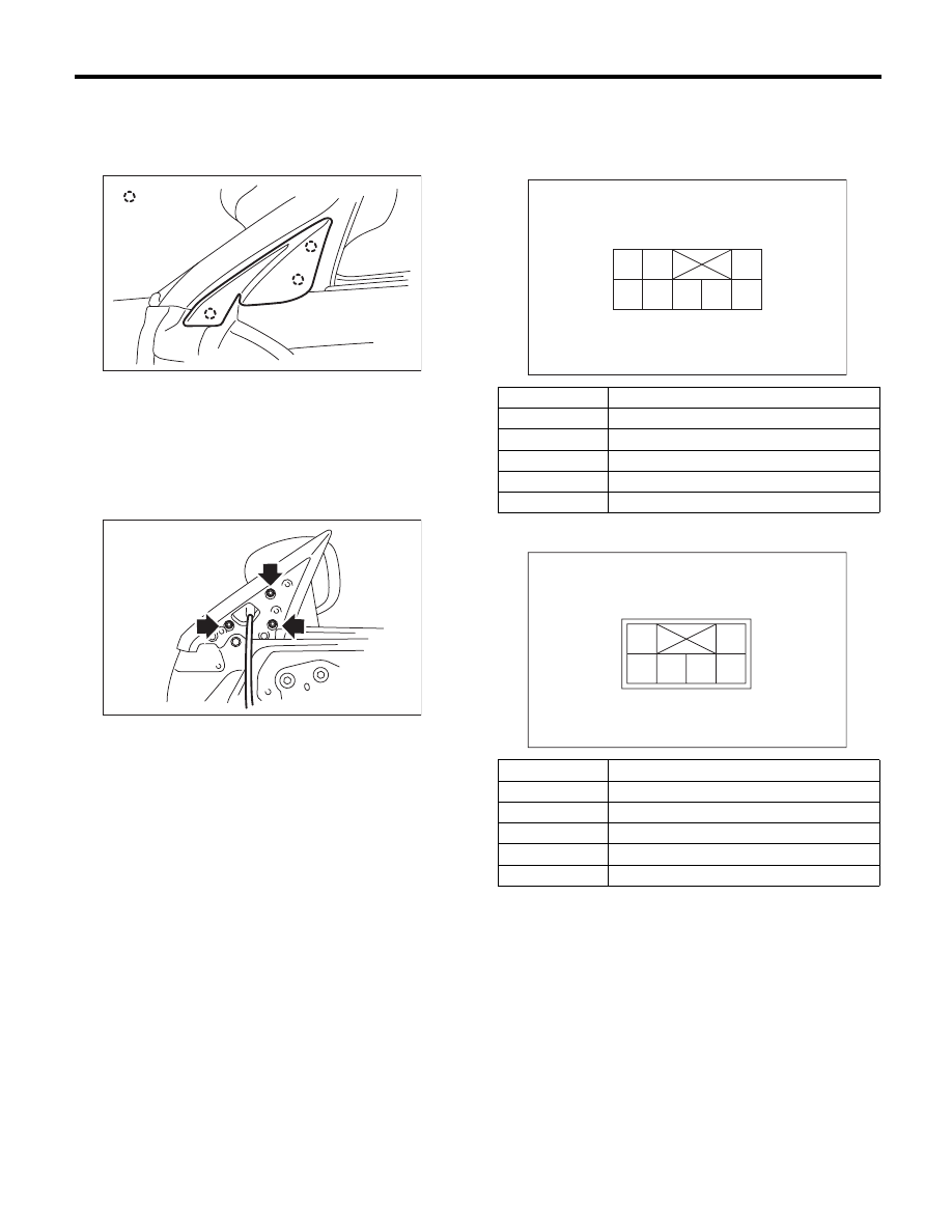
8. Outer Mirror Assembly
A: REMOVAL
1) Remove the mirror gusset cover.
2) Remove the door trim. <Ref. to EI-49, REMOV-
AL, Door Trim.>
3) Disconnect the outer mirror connector.
4) Remove the screws to remove outer mirror as-
sembly.
B: INSTALLATION
Install in the reverse order of removal.
C: INSPECTION
Check that the outer mirror moves properly when
the battery voltage is applied to terminals.
• Model with side turn signal light
• Model without side turn signal light
Replace the outer mirror assembly if defective.
(1) Hook
GW-00277
: (1)
GW-00278
Switch position
Terminal No.
OFF
—
UP
6 (+) and 3 (–)
DOWN
3 (+) and 6 (–)
LEFT
7 (+) and 3 (–)
RIGHT
3 (+) and 7 (–)
Switch position
Terminal No.
OFF
—
UP
4 (+) and 2 (–)
DOWN
2 (+) and 4 (–)
LEFT
5 (+) and 2 (–)
RIGHT
2 (+) and 5 (–)
GW-00408
1 2
3
4 5 6 7 8
GW-00409
1
2
3 4 5 6
GW-21
Outer Mirror
GLASS/WINDOWS/MIRRORS
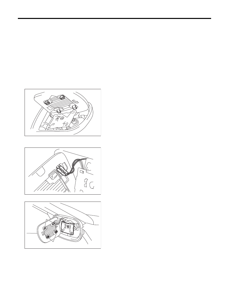
9. Outer Mirror
A: REPLACEMENT
CAUTION:
• When removing the mirror, be careful not to
damage the back surface of mirror with a flat tip
screwdriver.
• When installing the mirror, insert the hook
and clip securely.
1) Face the mirror upward.
2) Disconnect the ground cable from the battery.
(Model with mirror heater)
3) Use a flat tip screwdriver to remove clips (A).
4) Lift the lower mirror up to remove hooks (B).
5) Disconnect the mirror heater connector from
side of the mirror. (Model with mirror heater)
6) Catch the hooks (B) and install clips (A).
(A)
GW-00279
(B)
GW-00280
(B)
GW-00450
(A)
GW-22
Remote Control Mirror Switch
GLASS/WINDOWS/MIRRORS
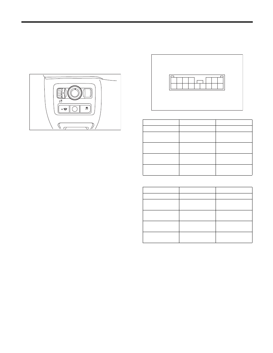
10.Remote Control Mirror
Switch
A: REMOVAL
1) Remove the instrument panel lower cover. <Ref.
to EI-51, REMOVAL, Instrument Panel Lower Cov-
er.>
2) Disconnect the connector.
3) Remove the remote control mirror switch from
instrument panel lower cover.
B: INSTALLATION
Install in the reverse order of removal.
C: INSPECTION
1. REMOTE CONTROL MIRROR SWITCH
Move the remote control mirror switch to each po-
sition and check continuity between terminals.
• Change over switch R
• Change over switch L
Replace the remote control mirror switch if defec-
tive.
L
R
OFF
OFF
GW-00391
Switch position
Terminal No.
Standard
OFF
—
1 M
: or more
UP
10 and 12
15 and 14
Less than 1
:
DOWN
10 and 15
12 and 14
Less than 1
:
LEFT
10 and 11
15 and 14
Less than 1
:
RIGHT
10 and 15
11 and 14
Less than 1
:
Switch position
Terminal No.
Standard
OFF
—
1 M
: or more
UP
10 and 8
15 and 14
Less than 1
:
DOWN
10 and 15
8 and 14
Less than 1
:
LEFT
10 and 9
15 and 14
Less than 1
:
RIGHT
10 and 15
9 and 14
Less than 1
:
GW-00283
9
14
7 6 5 4
3 2 1
8
13 12 11 10
16 15
Нет комментариевНе стесняйтесь поделиться с нами вашим ценным мнением.
Текст