Subaru Legacy IV (2008 year). Service manual — part 190

GD(H4SO)-62
Diagnostic Trouble Code (DTC) Detecting Criteria
GENERAL DESCRIPTION
• Abnormality Judgement
1) Judge as NG when the judgment value is larger than the threshold value after deceleration fuel cut.
Response time (diagnosis value) > threshold value
o abnormal
2) If the oxygen sensor voltage is small after recovering from a deceleration fuel cut, and remains small,
judge as NG.
Time Needed for Diagnosis: 1 time(s)
Malfunction Indicator Light Illumination: Illuminates when malfunction occurs in 2 continuous driving cy-
cles.
• Normality Judgement
1) Regardless of a deceleration fuel cut, if the response time (diagnosis value) when the oxygen sensor volt-
age has changed from rich to lean is shorter than the threshold value (judgment value), judge as a normal
condition.
Response time (diagnosis value)
d threshold value o normal
2) Do not judge as a normal condition.
Judge as OK and clear the NG if the following conditions are established.
Time Needed for Diagnosis: 1 time(s)
Judgement Value
Malfunction Criteria
Threshold Value
Shortest time change from lean (0.3 V
O
2
output) to rich (0.5 V) when voltage
changes from 0.25 V to 0.55 V
> 2000 ms
or
Longest time under 0.25 V
t 120000 ms
Judgement Value
Malfunction Criteria
Threshold Value
Shortest time change from lean (0.3 V
O
2
output) to rich (0.5 V) when voltage
changes from 0.25 V to 0.55 V
d 2000 ms
GD(H4SO)-63
Diagnostic Trouble Code (DTC) Detecting Criteria
GENERAL DESCRIPTION
AI: DTC P0140 O2 SENSOR CIRCUIT NO ACTIVITY DETECTED
(BANK1 SENSOR2)
1. OUTLINE OF DIAGNOSIS
Detect the rear oxygen sensor open or short circuit. Judge as NG when the rear oxygen sensor voltage can
be determined to be abnormal considering conditions such as intake air amount, engine coolant tempera-
ture, main feedback control and deceleration fuel cut.
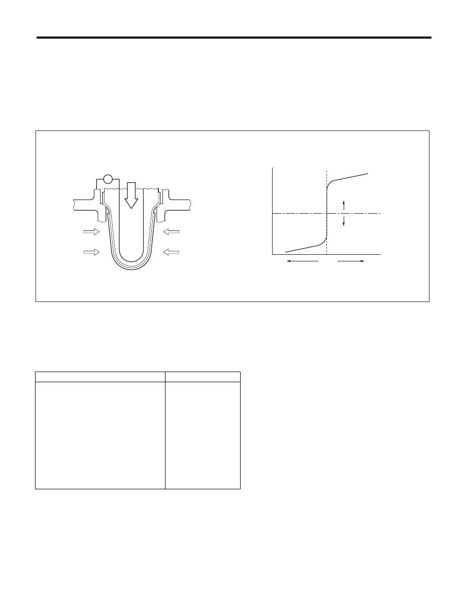
2. COMPONENT DESCRIPTION
3. ENABLE CONDITION (USED ONLY FOR MALFUNCTION JUDGMENT)
4. GENERAL DRIVING CYCLE
Perform the diagnosis once after starting the engine.
(A)
Electromotive force
(C)
Rich
(E)
Theoretical air fuel ratio
(B)
Air fuel ratio
(D)
Lean
(F)
Comparative voltage
(1)
Atmosphere
(2)
Exhaust gas
(3)
Electromotive force
Secondary Parameters
Enable Conditions
Closed loop control at the rear oxygen
sensor
In operation
Target output voltage of rear oxygen sensor
t 0.55 V + 0.05 V
Amount of intake air
t 10 g/s (0.35 oz/s)
Engine coolant temperature
t 75 °C (167 °F)
Misfire detection every 200 rotations
< 5 time(s)
Front oxygen (A/F) sensor compensation
coefficient
Not in limit value
Battery voltage
t 10.9 V
Deceleration fuel cut of 6000 ms or
more.
Experienced
EN-01696
(3)
V
(1)
(2)
(2)
(E)
(F)
(C)
(B)
(D)
(A)

GD(H4SO)-64
Diagnostic Trouble Code (DTC) Detecting Criteria
GENERAL DESCRIPTION
5. DIAGNOSTIC METHOD
• Abnormality Judgement
If the duration of time while the following conditions are met is longer than the time indicated, judge as NG.
Time Needed for Diagnosis: 200000 ms
Malfunction Indicator Light Illumination: Illuminates when malfunction occurs in 2 continuous driving cy-
cles.
• Normality Judgement
Judge as OK and clear the NG if the following conditions are established.
Judgement Value
Malfunction Criteria
Threshold Value
Minimum output voltage
> 0.15 V
or
Maximum output voltage
< 0.55 V
Judgement Value
Malfunction Criteria
Threshold Value
Diagnosis of the rear oxygen sensor volt-
age low side
Incomplete
Minimum output voltage
d 0.15 V
Maximum output voltage
t 0.55 V

GD(H4SO)-65
Diagnostic Trouble Code (DTC) Detecting Criteria
GENERAL DESCRIPTION
AJ:DTC P0171 SYSTEM TOO LEAN (BANK 1)
1. OUTLINE OF DIAGNOSIS
Detect fuel system malfunction by the amount of main feedback control.
Diagnostic method
Fuel system is diagnosed by comparing the target air fuel ratio calculated by ECM with the actual air fuel ratio
measured by sensor.
2. ENABLE CONDITION
3. GENERAL DRIVING CYCLE
Perform the diagnosis continuously at idling or at a constant speed after warming up the engine.
4. DIAGNOSTIC METHOD
• Abnormality Judgement
Compare the diagnosed value (fsobd) with the threshold value, and if a condition meeting the malfunction cri-
teria below continues for 10 s × 5 time(s) or more, judge that there is a fault in the fuel system.
Map2
Time Needed for Diagnosis: 10 s × 5 time(s)
Malfunction Indicator Light Illumination: Illuminates when malfunction occurs in 2 continuous driving cy-
cles.
Secondary Parameters
Enable Conditions
A/F main learning system
In operation
Engine coolant temperature
t 75 °C (167 °F)
Engine load change
< 0.02 g/rev (0 oz/rev)
Engine load
t Value of Map 1
Map1
Engine speed (rpm)
Idling
650
1000
1500
2000
2500
3000
3500
4000
4500
Measured value (g(oz)/rev)
Non-turbo
0.208
(0.01)
0.201
(0.01)
0.185
(0.01)
0.183
(0.01)
0.193
(0.01)
0.206
(0.01)
0.206
(0.01)
0.225
(0.01)
0.245
(0.01)
Judgement Value
Malfunction Criteria
Threshold Value
fsobd = (sglmd – tglmda) + faf + flaf
t Value of Map 2
In this case: sglmd = measured lambda
tglmda = target lambda
faf = main feedback compensation coef-
ficient every 64 milliseconds
flaf = main feedback learning compensa-
tion coefficient
U5 MODEL
Amount of air (g (oz)/s)
0 (0)
3.2
(0.11)
6.4
(0.23)
9.6
(0.34)
12.8
(0.45)
16
(0.56)
19.2
(0.68)
fsobdL1 (%)
1.4
1.4
1.332
1.25
1.25
1.25
1.25
EXCEPT FOR U5 MODEL
Amount of air (g (oz)/s)
0 (0)
3.2
(0.11)
6.4
(0.23)
9.6
(0.34)
12.8
(0.45)
16
(0.56)
19.2
(0.68)
fsobdL1 (%)
1.4
1.4
1.332
1.265
1.265
1.265
1.265
Нет комментариевНе стесняйтесь поделиться с нами вашим ценным мнением.
Текст