Subaru Legacy IV (2008 year). Service manual — part 502
LU(H6DO)-9
Oil Pump
LUBRICATION
4. Oil Pump
A: REMOVAL
1) Set the vehicle on a lift.
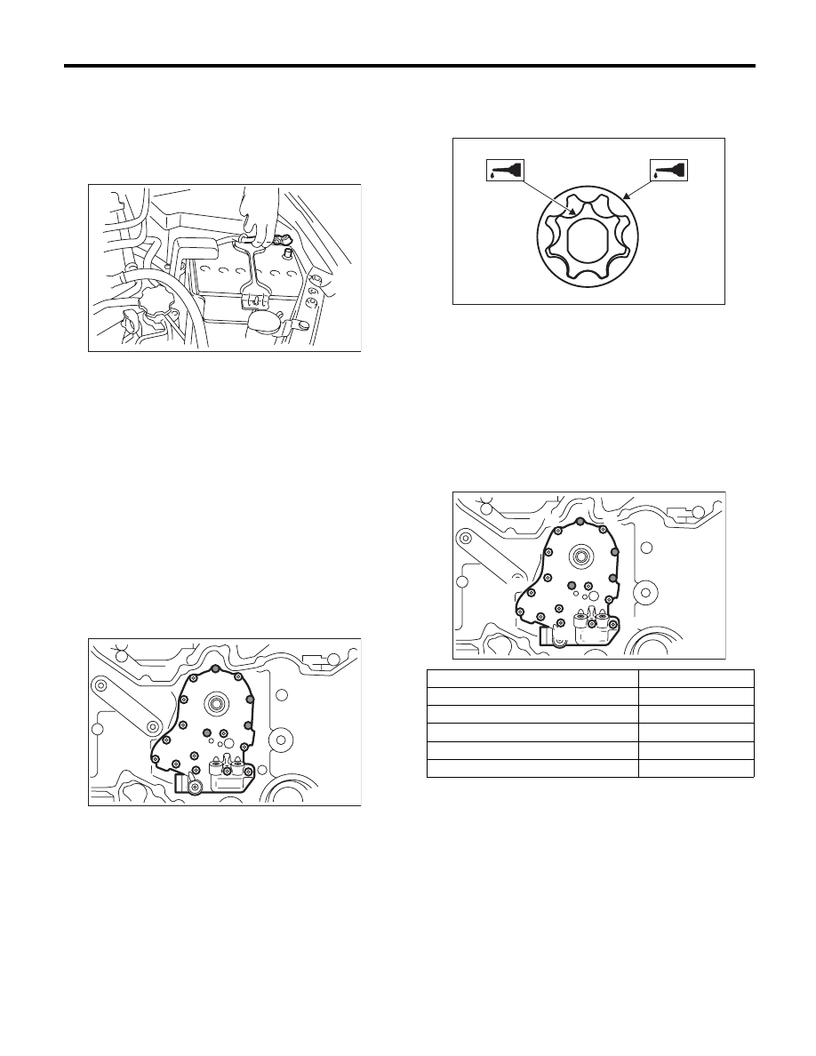
2) Remove the collector cover.
3) Disconnect the ground cable from battery.
4) Lift up the vehicle.
5) Remove the under cover.
6) Drain engine coolant. <Ref. to CO(H6DO)-10,
DRAINING OF ENGINE COOLANT, REPLACE-
MENT, Engine Coolant.>
7) Lower the vehicle.
8) Remove the radiator. <Ref. to CO(H6DO)-15,
REMOVAL, Radiator.>
9) Remove the V-belts. <Ref. to ME(H6DO)-42,
REMOVAL, V-belt.>
10) Remove the front chain cover. <Ref. to
ME(H6DO)-44, REMOVAL, Front Chain Cover.>
11) Remove the timing chain assembly. <Ref. to
ME(H6DO)-46, REMOVAL, Timing Chain Assem-
bly.>
12) Remove the crank sprocket.
13) Remove the oil pump cover.
14) Remove the inner rotor and outer rotor.
B: INSTALLATION
1) Apply a coat of engine oil to the whole area of in-
ner rotor and outer rotor.
2) Install the inner rotor to crankshaft and assemble
the outer rotor.
3) Install the oil pump cover.
4) Tighten the bolts in the numerical order as
shown in the figure.
CAUTION:
Make sure that the bolt is installed in correct
position.
Tightening torque:
6.4 N·m (0.7 kgf-m, 4.7 ft-lb)
5) Install the crank sprocket.
6) Install the timing chain assembly. <Ref. to
ME(H6DO)-47, INSTALLATION, Timing Chain As-
sembly.>
7) Install the front chain cover. <Ref. to ME(H6DO)-
44, INSTALLATION, Front Chain Cover.>
8) Install the V-belts. <Ref. to ME(H6DO)-42, IN-
STALLATION, V-belt.>
9) Install the radiator. <Ref. to CO(H6DO)-16, IN-
STALLATION, Radiator.>
10) Lift up the vehicle.
11) Install the under cover.
12) Lower the vehicle.
IN-00203
LU-02012
Bolt installing position
Bolt dimension
(1) and (3)
6 × 14 × 14
(2) and (4)
6 × 35 × 18
(5), (6), (7), (8), (9), (10) and (11)
6 × 35 × 15
(12), (15), (16) and (17)
6 × 16 × 16
(13) and (14)
6 × 26 × 15
LU-02032
LU-02013
(3)
(7)
(2)
(4)
(9)
(5)
(8)
(1) (6)
(12)
(13)
(14)
(15)
(16)
(17)
(11)
(10)
LU(H6DO)-10
Oil Pump
LUBRICATION
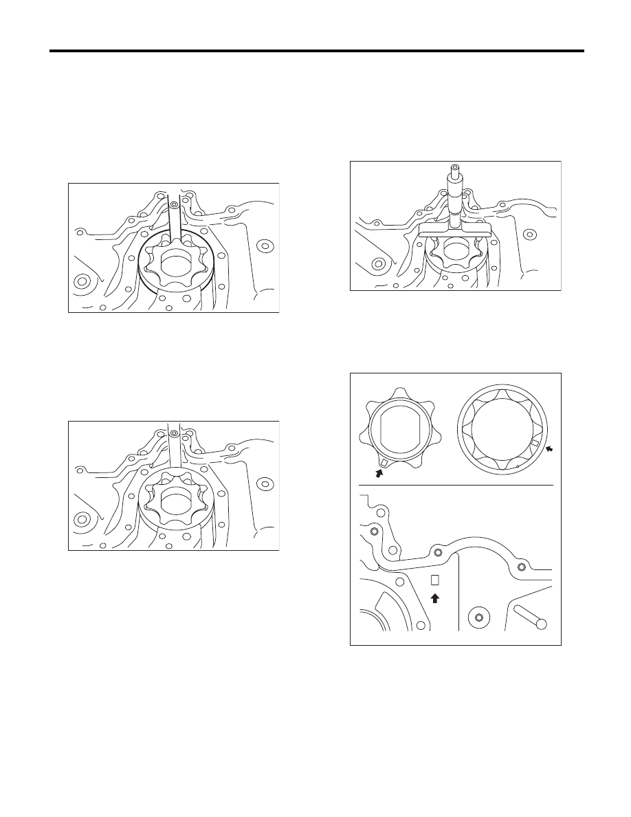
C: INSPECTION
1. TIP CLEARANCE
Measure the tip clearance of rotors. If the clearance
exceeds specification, replace the rotors as a
matched set.
Tip clearance:
Standard
0.04 — 0.14 mm (0.0016 — 0.0055 in)
2. CASE CLEARANCE
Measure the clearance between the outer rotor and
rear chain cover rotor housing. If the clearance ex-
ceeds the standard value, replace the outer rotor.
Case clearance:
Standard
0.110 — 0.175 mm (0.0043 — 0.0069 in)
3. SIDE CLEARANCE
Measure the clearance between oil pump inner ro-
tor and rear chain cover. If the clearance exceeds
specification, replace the rotors as a matched set.
Side clearance:
Specification
0.020 — 0.046 mm (0.0008 — 0.0018 in)
Perform the replacement part selection as follows.
• When replacing all of inner rotor, outer rotor and
rear chain cover with new parts, use those with
matching identification marks as there are identifi-
cation marks on those parts in the locations shown
on the figure.
LU-02014
LU-02015
LU-02016
ME-02734
LU(H6DO)-11
Oil Pump
LUBRICATION
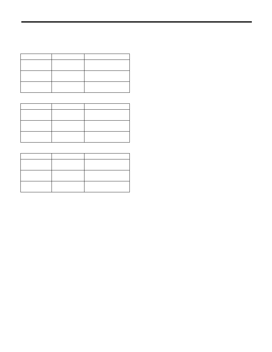
• When replacing any of inner rotor, outer rotor
and rear chain cover with a new part, select the
suitable size from the following table so that side
clearance is within the standard value.
4. OIL PUMP CASE
Check the worn shaft hole, clogged oil passage,
crank and other parts for faults.
Inner rotor
Identification
Part No.
Rotor thickness mm (in)
A
15015AA250
12.993 — 13.006
(0.51153 — 0.51205)
None
15015AA300
12.980 — 12.993
(0.51102 — 0.51153)
C
15015AA310
12.967 — 12.980
(0.51051 — 0.51102)
Outer rotor
Identification
Part No.
Rotor thickness mm (in)
A
15016AA250
12.993 — 13.006
(0.51153 — 0.51205)
None
15016AA300
12.980 — 12.993
(0.51102 — 0.51153)
C
15016AA310
12.967 — 12.980
(0.51051 — 0.51102)
Rear chain cover
Identification
Part No.
Rotor thickness mm (in)
A
13119AA020
13.026 — 13.039
(0.51295 — 0.51335)
B
13119AA050
13.013 — 13.026
(0.51232 — 0.51284)
C
13119AA060
13.000 — 13.013
(0.51181 — 0.51232)
LU(H6DO)-12
Oil Pump Relief Valve
LUBRICATION
5. Oil Pump Relief Valve
A: REMOVAL
1. REAR CHAIN COVER SIDE
Oil pump relief valve is integrated into oil pump cov-
er as one unit; therefore, refer to “Oil Pump” for re-
moval procedure. <Ref. to LU(H6DO)-9,
REMOVAL, Oil Pump.>
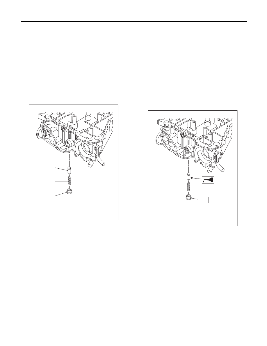
2. OIL PAN UPPER SIDE
1) Remove the oil pan. <Ref. to LU(H6DO)-13, RE-
MOVAL, Oil Pan and Strainer.>
2) Remove the plug, relief valve spring and relief
valve.
B: INSTALLATION
1. REAR CHAIN COVER SIDE
Oil pump relief valve is integrated into oil pump cov-
er as one unit; therefore, refer to “Oil Pump” for in-
stallation procedure. <Ref. to LU(H6DO)-9,
INSTALLATION, Oil Pump.>
2. OIL PAN UPPER SIDE
1) Install the relief valve, relief valve spring and
plug.
NOTE:
Apply engine oil to the relief valve.
Tightening torque:
T: 44 N·m (4.5 kgf-m, 32.5 ft-lb)
2) Install the oil pan. <Ref. to LU(H6DO)-13, IN-
STALLATION, Oil Pan and Strainer.>
C: INSPECTION
Check the worn shaft hole of oil pump relief valve
case, clogged oil passage, crank and other parts
for faults.
(1) Relief valve
(2) Relief valve spring
(3) Plug
(1)
LU-02033
(2)
(3)
LU-02034
T
Нет комментариевНе стесняйтесь поделиться с нами вашим ценным мнением.
Текст