Subaru Legacy IV (2008 year). Service manual — part 36
FU(H4SO)-33
Variable Valve Lift Diagnosis Oil Pressure Switch
FUEL INJECTION (FUEL SYSTEMS)
13.Variable Valve Lift Diagnosis
Oil Pressure Switch
A: REMOVAL
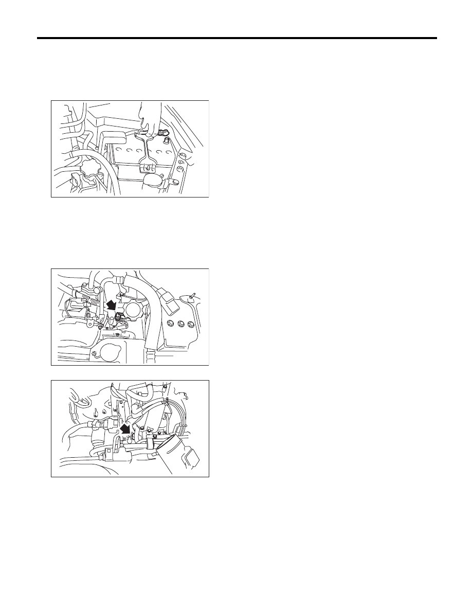
1) Disconnect the ground cable from battery.
2) Remove the air intake chamber. <Ref. to
IN(H4SO)-7, REMOVAL, Air Intake Chamber.>
3) Disconnect the connector from the variable
valve lift diagnosis oil pressure switch.
4) Remove the variable valve lift diagnosis oil pres-
sure switch.
• LH side
• RH side
B: INSTALLATION
Install in the reverse order of removal.
NOTE:
Apply liquid gasket to the variable valve lift diagno-
sis oil pressure switch threads.
Liquid gasket:
THREE BOND 1324 (Part No. 004403042) or
equivalent
Tightening torque:
17 N·m (1.7 kgf-m, 12.5 ft-lb)
IN-00203
FU-02731
FU-02732
FU(H4SO)-34
Oil Temperature Sensor
FUEL INJECTION (FUEL SYSTEMS)
14.Oil Temperature Sensor
A: REMOVAL
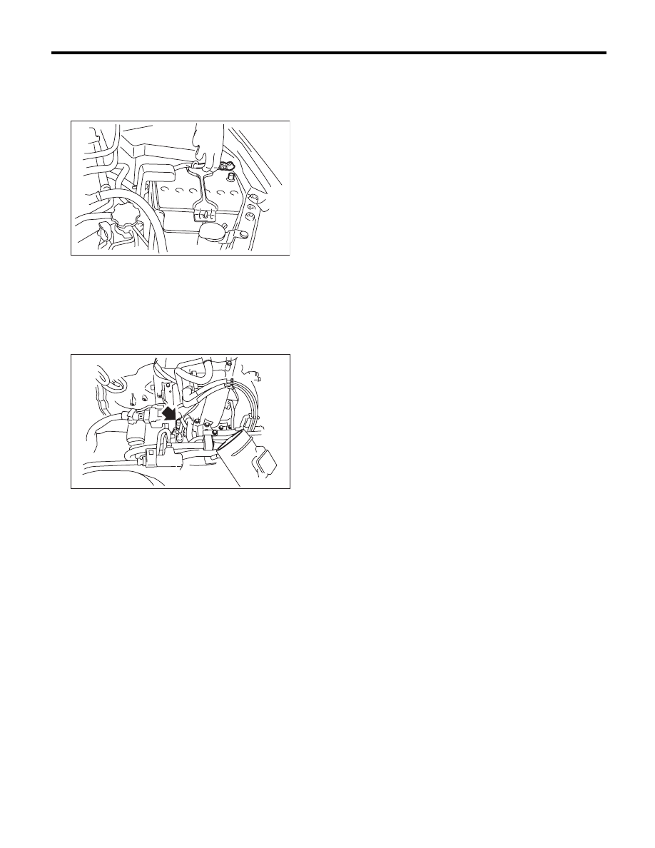
1) Disconnect the ground cable from battery.
2) Remove the air intake chamber. <Ref. to
IN(H4SO)-7, REMOVAL, Air Intake Chamber.>
3) Remove the engine harness connector from the
bracket.
4) Disconnect the connector from the oil tempera-
ture sensor.
5) Remove the oil temperature sensor.
B: INSTALLATION
Install in the reverse order of removal.
NOTE:
Apply liquid gasket to the oil temperature sensor
threads.
Liquid gasket:
THREE BOND 1324 (Part No. 004403042) or
equivalent
Tightening torque:
18 N·m (1.8 kgf-m, 13.3 ft-lb)
IN-00203
FU-02733
FU(H4SO)-35
Front Oxygen (A/F) Sensor
FUEL INJECTION (FUEL SYSTEMS)
15.Front Oxygen (A/F) Sensor
A: REMOVAL
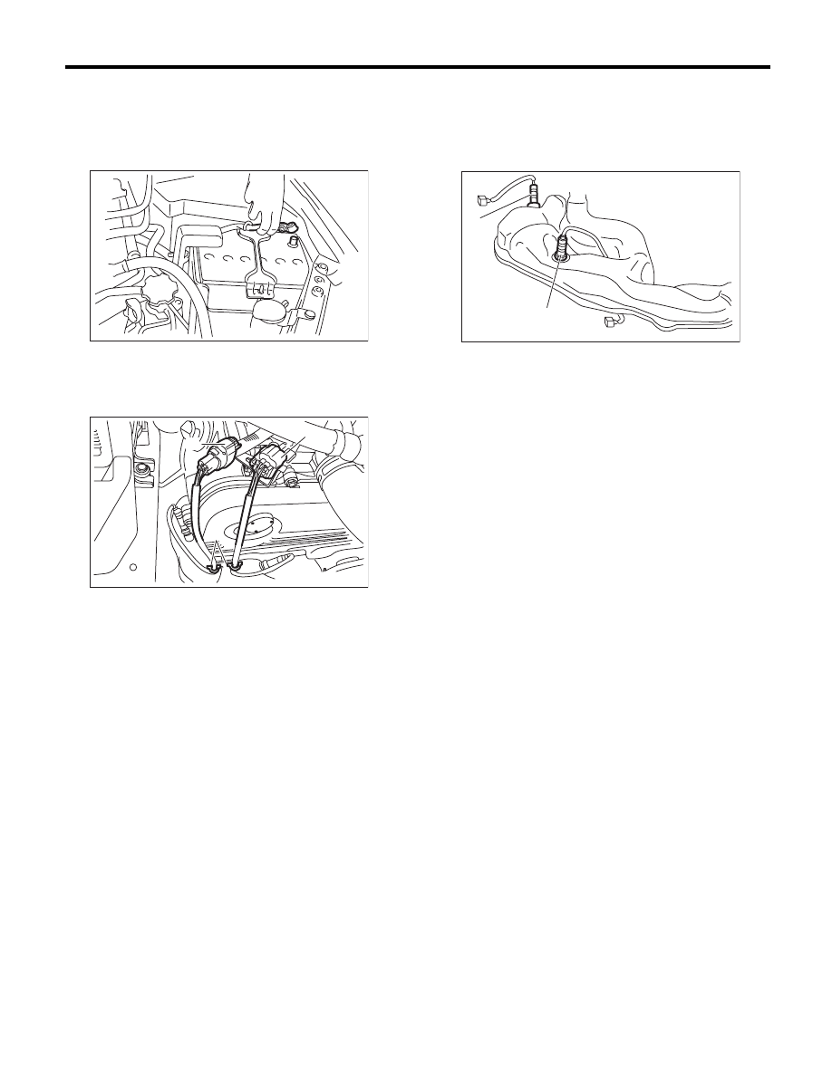
1) Set the vehicle on a lift.
2) Disconnect the ground cable from battery.
3) Remove the air intake duct. <Ref. to IN(H4SO)-
8, REMOVAL, Air Intake Duct.>
4) Remove the clip fastening the harness and dis-
connect the front oxygen (A/F) sensor connector.
5) Lift up the vehicle.
6) Remove the under cover.
7) Apply spray-type lubricant to the threaded por-
tion of front oxygen (A/F) sensor, and leave it for
one minute or more.
8) Remove the front oxygen (A/F) sensor.
CAUTION:
When removing the front oxygen (A/F) sensor,
wait until exhaust pipe cools, otherwise it will
damage the exhaust pipe.
(A) Front oxygen (A/F) sensor connector
(B) Rear oxygen sensor connector
(C) Clip
IN-00203
(C)
(B)
(A)
EX-02350
(A) Front oxygen (A/F) sensor
(B) Rear oxygen sensor
(A)
(B)
FU-02735
FU(H4SO)-36
Front Oxygen (A/F) Sensor
FUEL INJECTION (FUEL SYSTEMS)
B: INSTALLATION
CAUTION:
If lubricant is spilt onto the exhaust pipe, wipe it
off with cloth to avoid emission of smoke or
causing a fire.
1) Before installing front oxygen (A/F) sensor, ap-
ply anti-seize compound only to the threaded por-
tion of front oxygen (A/F) sensor to make the next
removal easier.
CAUTION:
Never apply anti-seize compound to the protec-
tor of front oxygen (A/F) sensor.
Anti-seize compound:
NEVER-SEEZ NSN, JET LUBE SS-30 or
equivalent
2) Install the front oxygen (A/F) sensor.
Tightening torque:
21 N·m (2.1 kgf-m, 15.5 ft-lb)
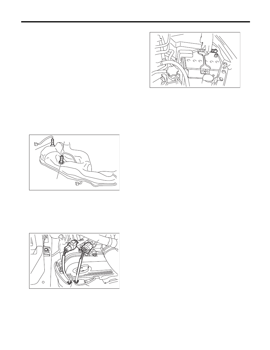
3) Install the under cover.
4) Lower the vehicle.
5) Connect the connector of front oxygen (A/F)
sensor connector and fasten the harness with clips.
6) Connect the ground cable to battery.
(A) Front oxygen (A/F) sensor
(B) Rear oxygen sensor
(A) Front oxygen (A/F) sensor connector
(B) Rear oxygen sensor connector
(C) Clip
(A)
(B)
FU-02735
(C)
(B)
(A)
EX-02350
IN-00203
Нет комментариевНе стесняйтесь поделиться с нами вашим ценным мнением.
Текст