Subaru Legacy IV (2008 year). Service manual — part 58
ME(H4SO)-28
Valve Clearance
MECHANICAL
13) Measure the valve clearance in #3, #2 and #4
cylinder in the same measurement procedure as #1
cylinder in this order.
NOTE:
• Be sure to set the cylinder pistons to their re-
spective top dead centers on compression stroke
before measuring valve clearances.
• By rotating the crank pulley clockwise every 180°
from the state that #1 cylinder piston is on the top
dead center of compression stroke, #3, #2 and #4
cylinder pistons come to the top dead center of
compression stroke in this order.
14) After inspection, install the related parts in the
reverse order of removal.
NOTE:
Use a new rocker cover gasket.
B: ADJUSTMENT
NOTE:
Adjustment of valve clearance should be per-
formed while engine is cold.
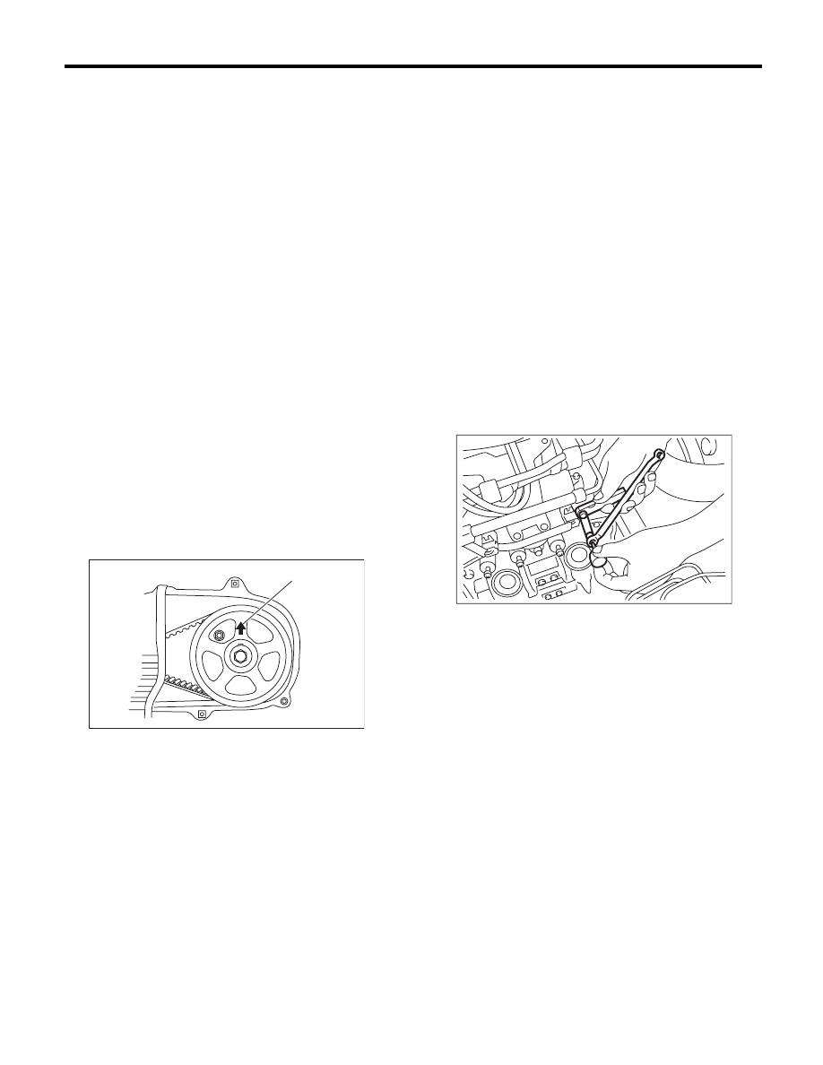
1) Set #1 cylinder piston to top dead center of com-
pression stroke by rotating the crank pulley clock-
wise using the socket wrench.
NOTE:
When the arrow mark (A) on cam sprocket LH is at
the top position, the #1 cylinder piston is at top
dead center of the compression stroke.
2) Adjust the #1 cylinder valve clearance.
(1) Loosen the valve rocker nut and screw.
(2) Set a suitable thickness gauge.
(3) While noting the valve clearance, tighten the
valve rocker adjusting screw.
(4) When the specified valve clearance is ob-
tained, tighten the valve rocker nut.
NOTE:
• Insert a thickness gauge in a direction as hori-
zontal as possible with respect to the valve stem
end face.
• Lift up the vehicle and adjust the exhaust valve
clearances.
Valve clearance:
Intake
0.20
r
0.04 mm (0.0079
r
0.0016 in)
Exhaust
0.25
r
0.04 mm (0.0098
r
0.0016 in)
Tightening torque:
9.75 N·m (1.0 kgf-m, 7.2 ft-lb)
3) Adjust the valve clearance in #3, #2 and #4 cyl-
inder in the same adjustment procedure as #1 cyl-
inder in this order.
NOTE:
• Be sure to set the cylinder pistons to their re-
spective top dead centers on compression stroke
before adjusting valve clearances.
• By rotating the crank pulley clockwise every 180°
from the state that #1 cylinder piston is on the top
dead center of compression stroke, #3, #2 and #4
cylinder pistons come to the top dead center of
compression stroke in this order.
4) Ensure the valve clearances of each cylinder are
within specifications. If necessary, readjust the
valve clearances.
ME-00200
( A )
ME-00203
ME(H4SO)-29
Engine Assembly
MECHANICAL
9. Engine Assembly
A: REMOVAL
1) Set the vehicle on a lift.
2) Open the front hood fully and support with the
front hood stay.
3) Remove the V-belt covers.
4) Collect the refrigerant from A/C system. <Ref. to
AC-22, PROCEDURE, Refrigerant Recovery Pro-
cedure.>
5) Release the fuel pressure. <Ref. to FU(H4SO)-
43, RELEASING OF FUEL PRESSURE, PROCE-
DURE, Fuel.>
6) Remove the battery. <Ref. to SC(H4SO)-20,
REMOVAL, Battery.>
7) Remove the air intake duct, air cleaner case and
air intake chamber. <Ref. to IN(H4SO)-8, REMOV-
AL, Air Intake Duct.> <Ref. to IN(H4SO)-5, RE-
MOVAL, Air Cleaner Case.> <Ref. to IN(H4SO)-7,
REMOVAL, Air Intake Chamber.>
8) Remove the under cover.
9) Remove the radiator from vehicle. <Ref. to
CO(H4SO)-19, REMOVAL, Radiator.>
10) Disconnect the A/C pressure hoses from A/C
compressor.
11) Remove the air intake chamber stay.
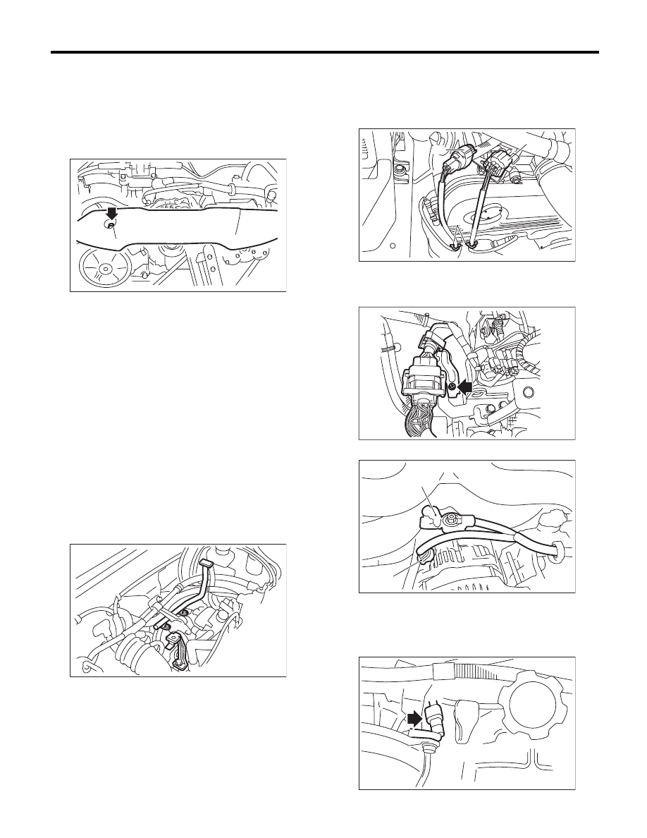
12) Disconnect the following connectors and cables.
(1) Disconnect the front oxygen (A/F) sensor
connector (A) and rear oxygen sensor connec-
tor (B) and remove the clip (C) fastening the
harness.
(2) Remove the bolt, and disconnect the engine
harness connector from the bulk head harness
connector and rear engine hanger.
(3) Generator connector and terminal
(4) A/C compressor connector
ME-03945
ME-00816
(A) Terminals
(B) Generator connector
(C)
(B)
(A)
EX-02350
FU-03924
ME-00818
(B)
(A)
ME-00819
ME(H4SO)-30
Engine Assembly
MECHANICAL
(5) Power steering pump switch connector
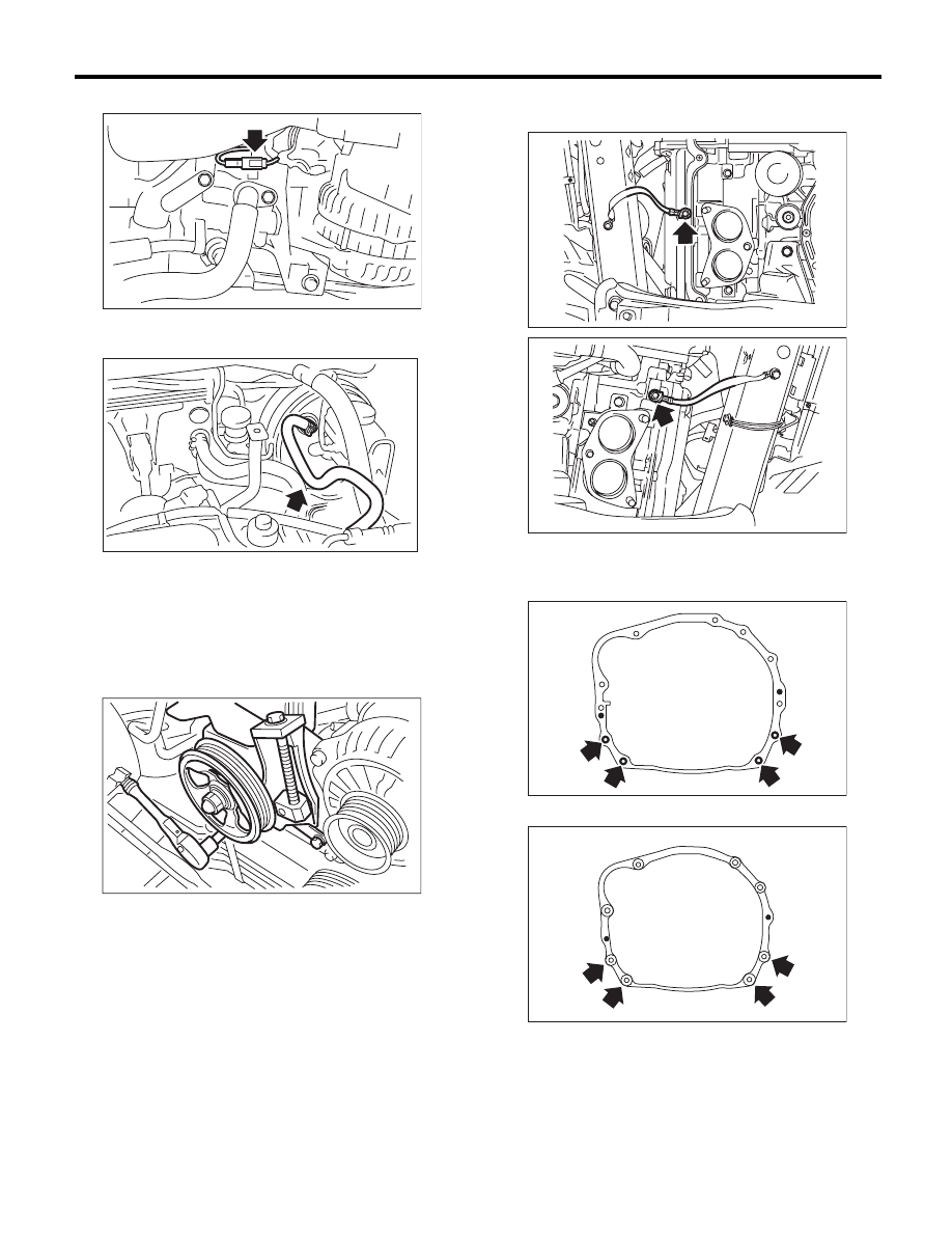
13) Disconnect the following hoses.
(1) Brake booster vacuum hose
(2) Heater inlet and outlet hoses
14) Remove the power steering pump.
(1) Remove the front side belts. <Ref. to
ME(H4SO)-38, FRONT SIDE BELT, REMOV-
AL, V-belt.>
(2) Remove the bolts which secure the power
steering pump to the bracket.
(3) Place the power steering pump on the right
side wheel apron.
15) Lift up the vehicle.
16) Remove the front and center exhaust pipes.
<Ref. to EX(H4SO)-4, REMOVAL, Front Exhaust
Pipe.>
17) Disconnect the ground cable on the engine
side.
18) Remove the bolts and nuts which hold lower
side of transmission to engine.
• AT model
• MT model
ME-03004
ME-02698
ME-00037
ME-03376
ME-03377
AT-00108
MT-00077
ME(H4SO)-31
Engine Assembly
MECHANICAL
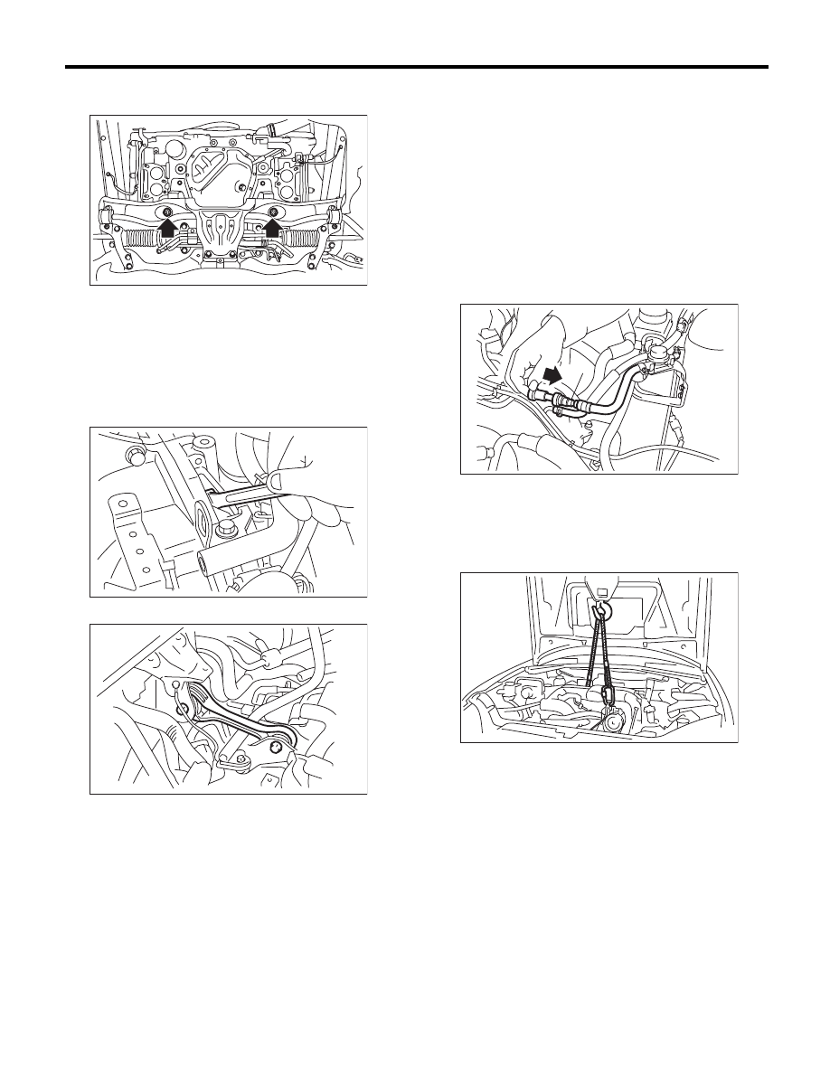
19) Remove the nuts which hold the engine mount
to the front crossmember.
20) Separate the torque converter clutch from drive
plate. (AT model)
(1) Lower the vehicle.
(2) Remove the service hole plug.
(3) Insert the wrench into the crank pulley bolt
and rotate the crank pulley to remove the bolts
which hold torque converter clutch to drive
plate.
21) Remove the pitching stopper.
22) Disconnect the fuel delivery hose from the fuel
pipe.
(1) Disconnect the quick connector on the fuel
delivery line by pushing the ST in the direction
of the arrow.
ST
42099AE000
QUICK CONNECTOR
RELEASE
(2) Remove the clip and disconnect the evapo-
ration hose from the pipe.
CAUTION:
• Be careful not to spill fuel.
• Catch the fuel from hoses using a container
or cloth.
23) Support the engine with a lifting device and
wire ropes.
LU-02470
ME-00212
AT-03877
(A) Fuel delivery hose
(B) Evaporation hose
(A)
(B)
FU-02715
LU-00222
Нет комментариевНе стесняйтесь поделиться с нами вашим ценным мнением.
Текст