Subaru Legacy IV (2008 year). Service manual — part 958
PB-3
General Description
PARKING BRAKE
2. PARKING BRAKE CABLE
C: CAUTION
• Wear appropriate work clothing, including a cap,
protective goggles and protective shoes when per-
forming any work.
• Before removal, installation or disassembly, be
sure to clarify the failure. Avoid unnecessary re-
moval, installation, disassembly and replacement.
• Vehicle components are extremely hot after driv-
ing. Be wary of receiving burns from heated parts.
• Use SUBARU genuine grease etc. or equivalent.
Do not mix grease etc. of different grades or man-
ufacturers.
• Be sure to tighten fasteners including bolts and
nuts to the specified torque.
• Place shop jacks or rigid racks at the specified
points.
• Before securing a part in a vise, place cushioning
material such as wood blocks, aluminum plate or
cloth between the part and the vise.
• Make sure grease does not come into contact
with the parking shoes.
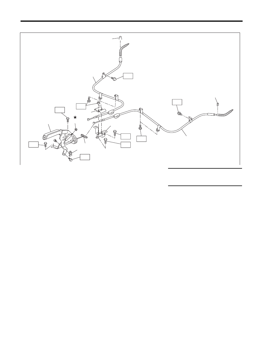
(1)
Parking brake lever
(6)
Clamp
Tightening torque:N·m (kgf-m, ft-lb)
(2)
Parking brake switch
(7)
Parking brake cable RH
T1: 18 (1.8, 13.0)
(3)
Adjusting nut (Self-locking nut)
(8)
Clamp
T2: 33 (3.4, 24.3)
(4)
Equalizer
(9)
Parking brake cable LH
(5)
Bracket
PB-00113
T1
T2
T1
T1
T1
(5)
(6)
(7)
(8)
(9)
(8)
T2
T1
T1
(1)
(3)
T1
(2)
(4)
PB-4
Parking Brake Lever
PARKING BRAKE
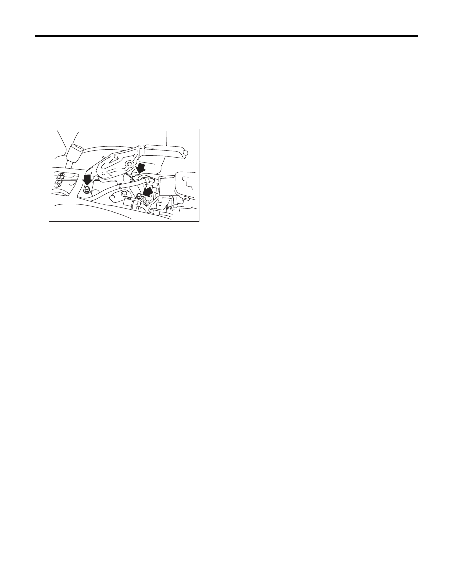
2. Parking Brake Lever
A: REMOVAL
1) Set the wheel stoppers to tires.
2) Remove the console box.
3) Disconnect the parking brake switch connector.
4) Remove the parking cable adjusting nut (self-
locking nut).
5) Remove the parking brake lever.
B: INSTALLATION
1) Install in the reverse order of removal.
Tightening torque:
Parking brake lever
18 N·m (1.8 kgf-m, 13.0 ft-lb)
2) Install a new adjusting nut (self-locking nut).
3) Be sure to adjust the lever stroke. <Ref. to PB-4,
ADJUSTMENT, Parking Brake Lever.>
C: INSPECTION
1) Operate the parking brake lever 3 to 4 times and
fully return the lever.
2) While slowly pulling the parking brake lever up-
ward, count the notches.
Lever stroke:
5 to 6 notches when pulled with a force of
200 N (20.4 kgf, 45 lb)
If it is not within the specified value, adjust the park-
ing brake. <Ref. to PB-8, ADJUSTMENT, Parking
Brake Assembly (Rear Disc Brake).>
D: ADJUSTMENT
Adjust the parking lever stroke. <Ref. to PB-8, LE-
VER STROKE, ADJUSTMENT, Parking Brake As-
sembly (Rear Disc Brake).>
PB-00053
PB-5
Parking Brake Cable
PARKING BRAKE
3. Parking Brake Cable
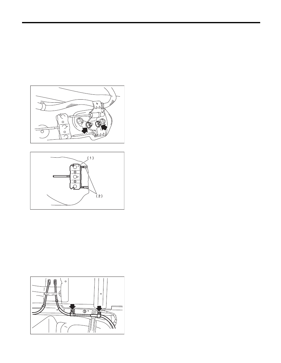
A: REMOVAL
1) Remove the rear seat cushion.
2) Remove the console box.
3) Remove the parking cable adjusting nut (self-
locking nut).
4) Remove the parking brake lever. <Ref. to PB-4,
REMOVAL, Parking Brake Lever.>
5) Roll up the floor mat and remove the clamps.
6) Remove the inner cable end from equalizer.
7) Lift up the vehicle, and then remove the rear wheels.
8) Remove the parking brake cable from rear
brake. <Ref. to PB-6, REMOVAL, Parking Brake
Assembly (Rear Disc Brake).>
9) Remove the clamp from the rear brake.
10) Remove the cable clamp from the rear arm
bracket.
11) Remove the cable clamp from rear floor.
12) Remove the cable assembly.
B: INSTALLATION
1) Install in the reverse order of removal.
NOTE:
Be sure to pass the cable through the tunnel in the
cable guide.
2) Be sure to adjust the lever stroke. <Ref. to PB-4,
ADJUSTMENT, Parking Brake Lever.>
C: INSPECTION
Check and replace the removed cable if damaged,
rusty or faulty.
1) Check the cable for smooth operation.
2) Check the inner cable for damage and rust.
3) Check the outer cable for damage, bends and
cracks.
4) Check the boot for damage, cracks, and corro-
sion.
(1) Equalizer
(2) Inner cable end
PB-00078
PB-00008
PB-00026
PB-6
Parking Brake Assembly (Rear Disc Brake)
PARKING BRAKE
4. Parking Brake Assembly
(Rear Disc Brake)
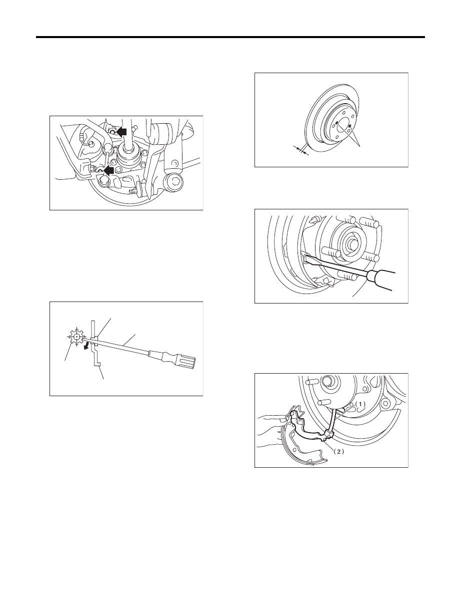
A: REMOVAL
1) Release the parking brake.
2) Remove the two mounting bolts and remove the
brake caliper assembly.
3) Suspend the brake caliper assembly so that the
hose is not stretched.
4) Remove the disc rotor.
NOTE:
If the disc rotor is difficult to remove, try the follow-
ing two methods in order.
(1) Turn the adjusting screw using a flat tip
screwdriver until the brake shoe moves ade-
quately away from the disc rotor.
(2) If disc rotor is seized on the hub, drive the
disc rotor out by pushing two 8 mm bolts in
holes B on the rotor.
5) Remove the shoe return spring from the parking
brake assembly.
6) Remove the front shoe hold down spring and
pin.
7) Remove the strut and strut spring.
8) Remove the adjuster assembly from the parking
brake assembly.
9) Remove the brake shoe.
10) Remove the rear shoe hold down spring and
pin with pliers.
11) Remove the parking brake cable from lever.
12) Using a flat tip screwdriver, raise the retainer.
Remove the parking lever and washer from brake
shoe.
(1) Adjuster
(2) Adjusting hole cover (rubber)
(3) Flat tip screwdriver
(4) Back plate
BR-00346
(1)
(4)
(2)
(3)
BR-00155
(1) Parking brake cable
(2) Lever
A
B
BR-00036
PB-00028
PB-00014
Нет комментариевНе стесняйтесь поделиться с нами вашим ценным мнением.
Текст