Subaru Legacy IV (2008 year). Service manual — part 121
EN(H4SO)(diag)-87
Diagnostic Procedure with Diagnostic Trouble Code (DTC)
ENGINE (DIAGNOSTICS)
20.Diagnostic Procedure with Diagnostic Trouble Code (DTC)
A: DTC P0026 INTAKE VALVE CONTROL SOLENOID CIRCUIT RANGE/
PERFORMANCE (BANK 1)
DTC DETECTING CONDITION:
• Immediately at fault recognition
• GENERAL DESCRIPTION <Ref. to GD(H4SO)-8, DTC P0026 INTAKE VALVE CONTROL SOLENOID
CIRCUIT RANGE/PERFORMANCE (BANK 1), Diagnostic Trouble Code (DTC) Detecting Criteria.>
TROUBLE SYMPTOM:
Improper idling
CAUTION:
After repair or replacement of faulty parts, perform Clear Memory Mode <Ref. to EN(H4SO)(diag)-50,
OPERATION, Clear Memory Mode.>, and Inspection Mode <Ref. to EN(H4SO)(diag)-41, PROCEDURE,
Inspection Mode.>.
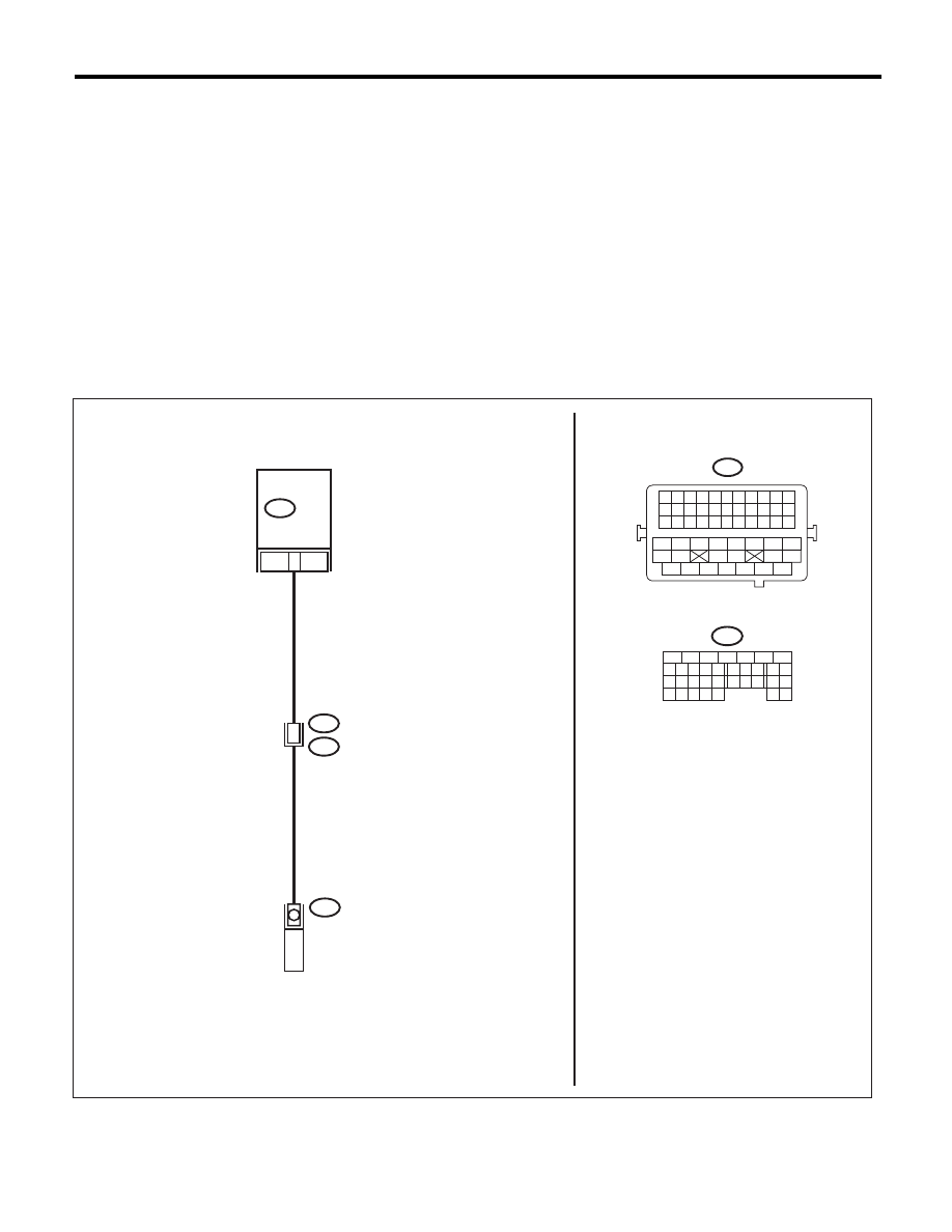
WIRING DIAGRAM:
EN-04025
B134
31
B21
E2
21
ECM
B21
1
VVL DIAGNOSIS
OIL PRESSURE SWITCH
RH
E71
B134
8
5
6
10 11 12 13 14 15
7
2
1
3
4
16
30
19 20
22
28 29
9
17
18
25
21
23 24
32
31
26 27
33 34
1 2 3 4 5 6 7 8 9 10 11
12 13 14 15 16 17 18 19 20 21 22
23 24 25 26 27 28 29 30 31 32 33
34
35
42
43
36
37
38
39
48
49
50
51
52
53
54
40
41
44
45
46
47

EN(H4SO)(diag)-88
Diagnostic Procedure with Diagnostic Trouble Code (DTC)
ENGINE (DIAGNOSTICS)
Step
Check
Yes
No
1
CHECK HARNESS BETWEEN ECM AND
VARIABLE VALVE LIFT DIAGNOSIS OIL
PRESSURE SWITCH.
1) Warm up the engine.
2) Turn the ignition switch to OFF.
3) Disconnect the connectors from ECM and
variable valve lift diagnosis oil pressure switch.
4) Measure the resistance of harness between
ECM and variable valve lift diagnosis oil pres-
sure switch connector.
Connector & terminal
(B134) No. 31 — (E71) No. 1:
Is the resistance less than 1
:? Go to step 2.
Repair the harness
and connector.
NOTE:
In this case, repair
the following item:
• Open circuit in
harness between
ECM and variable
valve lift diagnosis
oil pressure switch
connector
• Poor contact of
coupling connector
2
CHECK HARNESS BETWEEN ECM AND
VARIABLE VALVE LIFT DIAGNOSIS OIL
PRESSURE SWITCH.
Measure the resistance between variable valve
lift diagnosis oil pressure switch connector and
engine ground.
Connector & terminal
(E71) No. 1 — Engine ground:
Is the resistance 1 M
: or
more?
Go to step 3.
Repair the ground
short circuit of har-
ness between
ECM and variable
valve lift diagnosis
oil pressure switch
connector.
3
CHECK HARNESS BETWEEN ECM AND
VARIABLE VALVE LIFT DIAGNOSIS OIL
PRESSURE SWITCH.
1) Turn the ignition switch to ON.
2) Measure the voltage between variable valve
lift diagnosis oil pressure switch connector and
engine ground.
Connector & terminal
(E71) No. 1 (+) — Engine ground (–):
Is the voltage 10 V or more?
Repair the short
circuit of harness
to power supply
between ECM and
variable valve lift
diagnosis oil pres-
sure switch con-
nector.
Go to step 4.
4
CHECK DTC.
1) Perform the Clear Memory Mode.
2) After idling the engine, check the DTC.
NOTE:
For detailed procedure, refer to “Clear Memory
Mode”. <Ref. to EN(H4SO)(diag)-50, Clear
Memory Mode.>
Is DTC displayed?
Replace the oil
switching solenoid
valve. <Ref. to
ME(H4SO)-89, Oil
Switching Solenoid
Valve.> Go to step
5.
End.
5
CHECK DTC.
1) Perform the Clear Memory Mode.
2) After idling the engine, check the DTC.
NOTE:
For detailed procedure, refer to “Clear Memory
Mode”. <Ref. to EN(H4SO)(diag)-50, Clear
Memory Mode.>
Is DTC displayed?
Check for oil rout-
ing.
End.
EN(H4SO)(diag)-89
Diagnostic Procedure with Diagnostic Trouble Code (DTC)
ENGINE (DIAGNOSTICS)
B: DTC P0028 INTAKE VALVE CONTROL SOLENOID CIRCUIT RANGE/
PERFORMANCE (BANK 2)
DTC DETECTING CONDITION:
• Immediately at fault recognition
• GENERAL DESCRIPTION <Ref. to GD(H4SO)-10, DTC P0028 INTAKE VALVE CONTROL SOLENOID
CIRCUIT RANGE/PERFORMANCE (BANK 2), Diagnostic Trouble Code (DTC) Detecting Criteria.>
TROUBLE SYMPTOM:
Improper idling
CAUTION:
After repair or replacement of faulty parts, perform Clear Memory Mode <Ref. to EN(H4SO)(diag)-50,
OPERATION, Clear Memory Mode.>, and Inspection Mode <Ref. to EN(H4SO)(diag)-41, PROCEDURE,
Inspection Mode.>.
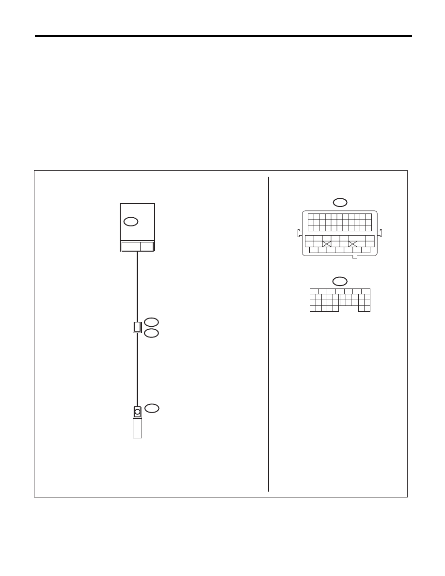
WIRING DIAGRAM:
EN-04026
1
8
5
6
10 11 12 13 14 15
7
2
1
3
4
16
30
19 20
22
28 29
9
17
18
25
21
23 24
32
31
26 27
33 34
1 2 3 4 5 6 7 8 9 10 11
12 13 14 15 16 17 18 19 20 21 22
23 24 25 26 27 28 29 30 31 32 33
34
35
42
43
36
37
38
39
48
49
50
51
52
53
54
40
41
44
45
46
47
B21
E2
22
B134
32
ECM
VVL DIAGNOSIS
OIL PRESSURE SWITCH LH
E72
B21
B134

EN(H4SO)(diag)-90
Diagnostic Procedure with Diagnostic Trouble Code (DTC)
ENGINE (DIAGNOSTICS)
Step
Check
Yes
No
1
CHECK HARNESS BETWEEN ECM AND
VARIABLE VALVE LIFT DIAGNOSIS OIL
PRESSURE SWITCH.
1) Warm up the engine.
2) Turn the ignition switch to OFF.
3) Disconnect the connectors from ECM and
variable valve lift diagnosis oil pressure switch.
4) Measure the resistance of harness between
ECM and variable valve lift diagnosis oil pres-
sure switch connector.
Connector & terminal
(B134) No. 32 — (E72) No. 1:
Is the resistance less than 1
:? Go to step 2.
Repair the harness
and connector.
NOTE:
In this case, repair
the following item:
• Open circuit in
harness between
ECM and variable
valve lift diagnosis
oil pressure switch
connector
• Poor contact of
coupling connector
2
CHECK HARNESS BETWEEN ECM AND
VARIABLE VALVE LIFT DIAGNOSIS OIL
PRESSURE SWITCH.
Measure the resistance between variable valve
lift diagnosis oil pressure switch connector and
engine ground.
Connector & terminal
(E72) No. 1 — Engine ground:
Is the resistance 1 M
: or
more?
Go to step 3.
Repair the ground
short circuit of har-
ness between
ECM and variable
valve lift diagnosis
oil pressure switch
connector.
3
CHECK HARNESS BETWEEN ECM AND
VARIABLE VALVE LIFT DIAGNOSIS OIL
PRESSURE SWITCH.
1) Turn the ignition switch to ON.
2) Measure the voltage between variable valve
lift diagnosis oil pressure switch connector and
engine ground.
Connector & terminal
(E72) No. 1 (+) — Engine ground (–):
Is the voltage 10 V or more?
Repair the short
circuit of harness
to power supply
between ECM and
variable valve lift
diagnosis oil pres-
sure switch con-
nector.
Go to step 4.
4
CHECK DTC.
1) Perform the Clear Memory Mode.
2) After idling the engine, check the DTC.
NOTE:
For detailed procedure, refer to “Clear Memory
Mode”. <Ref. to EN(H4SO)(diag)-50, Clear
Memory Mode.>
Is DTC displayed?
Replace the oil
switching solenoid
valve. <Ref. to
ME(H4SO)-89, Oil
Switching Solenoid
Valve.> Go to step
5.
End.
5
CHECK DTC.
1) Perform the Clear Memory Mode.
2) After idling the engine, check the DTC.
NOTE:
For detailed procedure, refer to “Clear Memory
Mode”. <Ref. to EN(H4SO)(diag)-50, Clear
Memory Mode.>
Is DTC displayed?
Check for oil rout-
ing.
End.
Нет комментариевНе стесняйтесь поделиться с нами вашим ценным мнением.
Текст