Subaru Legacy IV (2008 year). Service manual — part 545

EN(H6DO)(diag)-153
Diagnostic Procedure with Diagnostic Trouble Code (DTC)
ENGINE (DIAGNOSTICS)
Step
Check
Yes
No
1
CHECK ENGINE COOLANT TEMPERATURE
SENSOR.
Measure the resistance between engine cool-
ant temperature sensor terminals when the
engine coolant is cold and after warmed up.
Terminals
No. 1 — No. 2:
Is the resistance of engine cool-
ant temperature sensor differ-
ent between when engine
coolant is cold and after
warmed up?
Repair the poor
contact of ECM
connector.
Replace the
engine coolant
temperature sen-
sor. <Ref. to
FU(H6DO)-20,
Engine Coolant
Temperature Sen-
sor.>

EN(H6DO)(diag)-154
Diagnostic Procedure with Diagnostic Trouble Code (DTC)
ENGINE (DIAGNOSTICS)
AJ:DTC P0128 COOLANT THERMOSTAT (ENGINE COOLANT TEMPERATURE
BELOW THERMOSTAT REGULATING TEMPERATURE)
DTC DETECTING CONDITION:
• Two consecutive driving cycles with fault
• GENERAL DESCRIPTION <Ref. to GD(H6DO)-49, DTC P0128 COOLANT THERMOSTAT (ENGINE
COOLANT TEMPERATURE BELOW THERMOSTAT REGULATING TEMPERATURE), Diagnostic Trouble
Code (DTC) Detecting Criteria.>
TROUBLE SYMPTOM:
Thermostat remains open.
CAUTION:
After repair or replacement of faulty parts, perform Clear Memory Mode <Ref. to EN(H6DO)(diag)-52,
OPERATION, Clear Memory Mode.>, and Inspection Mode <Ref. to EN(H6DO)(diag)-44, PROCEDURE,
Inspection Mode.>.
Step
Check
Yes
No
1
CHECK ENGINE COOLANT.
Are the coolant level and mix-
ture ratio of engine coolant to
anti-freeze solution correct?
Go to step 2.
Replace the
engine coolant.
<Ref. to
CO(H6DO)-10,
REPLACEMENT,
Engine Coolant.>
2
CHECK RADIATOR FAN.
1) Start the engine.
2) Check the radiator fan operation.
Does the radiator fan continu-
ously rotate for 3 minutes or
more during idling?
Repair radiator fan
circuit. <Ref. to
CO(H6DO)-19,
Radiator Main Fan
and Fan Motor.>
and <Ref. to
CO(H6DO)-22,
Radiator Sub Fan
and Fan Motor.>
Replace the ther-
mostat. <Ref. to
CO(H6DO)-13,
Thermostat.>
EN(H6DO)(diag)-155
Diagnostic Procedure with Diagnostic Trouble Code (DTC)
ENGINE (DIAGNOSTICS)
AK:DTC P0131 O2 SENSOR CIRCUIT LOW VOLTAGE (BANK 1 SENSOR 1)
DTC DETECTING CONDITION:
• Immediately at fault recognition
• GENERAL DESCRIPTION <Ref. to GD(H6DO)-51, DTC P0131 O2 SENSOR CIRCUIT LOW VOLTAGE
(BANK 1 SENSOR 1), Diagnostic Trouble Code (DTC) Detecting Criteria.>
CAUTION:
After repair or replacement of faulty parts, perform Clear Memory Mode <Ref. to EN(H6DO)(diag)-52,
OPERATION, Clear Memory Mode.>, and Inspection Mode <Ref. to EN(H6DO)(diag)-44, PROCEDURE,
Inspection Mode.>.
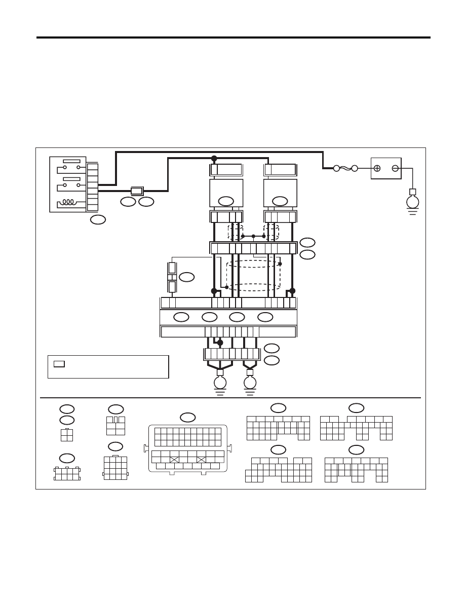
WIRING DIAGRAM:
SBF-5
BATTERY
E
E3
B22
B47
1
2
3
5
4
6
MAIN RELAY
E3
B22
8
: TERMINAL No. OPTIONAL ARRANGEMENT
AMONG 1, 2, 5 AND 6
*
3
4
5
6
1
2
B47
1 2 3 4
5 6 7 8
9 10 11 12
13 14 15 16
B22
3 4
1 2
E47
E24
16
10 11 12 13 14 15
25
24
30
9
8
7
17 18 19 20
28
21 22 23
29
32
31
1
2
3
4
5
6
27
26
33 34 35
B136
C:
5
6
7
8
2
1
9
4
3
10
22 23
11 12 13 14 15
24 25
26
16 17
18 19 20 21
27
28 29
30 31
B137
D:
1 2 3 4
5 6 7 8
B138
5
6
7
8
2
1
9
4
3
10
24
22 23
25
11 12 13 14 15
26 27
28
16 17 18 19
20 21
29 30 31
32 33
34 35
B135
B:
5
6
7
8
2
1
9
4
3
10
24
22 23
25
11 12 13 14 15
26 27
28
16 17
18 19 20 21
33 34
29
32
30 31
B134
A:
B11
2
E24
FRONT
OXYGEN (A/F)
SENSOR LH
3
4
B10
1
B7
B6
C2
C3
B8
4
1
3
B9
ECM
B135
B:
B134
A:
B137
D:
B136
C:
D3
A3
D2
D1
D7
A5
35
34
52
36
37
B21
E2
E
E
EN-06867
B21
1 2 3 4 5 6 7 8 9 10 11
12 13 14 15 16 17 18 19 20 21 22
23 24 25 26 27 28 29 30 31 32 33
34
35
42
43
36
37
38
39
48
49
50
51
52
53
54
40
41
44
45
46
47
2
E47
FRONT
OXYGEN (A/F)
SENSOR RH
5
6
7
4
2
1
3
B138
*
*
B1

EN(H6DO)(diag)-156
Diagnostic Procedure with Diagnostic Trouble Code (DTC)
ENGINE (DIAGNOSTICS)
Step
Check
Yes
No
1
CHECK FRONT OXYGEN (A/F) SENSOR
CONNECTOR AND COUPLING CONNEC-
TOR.
Has water entered the connec-
tor?
Completely
remove any water
inside.
Go to step 2.
2
CHECK HARNESS BETWEEN ECM AND
FRONT OXYGEN (A/F) SENSOR CONNEC-
TOR.
1) Turn the ignition switch to OFF.
2) Disconnect the connectors from ECM and
front oxygen (A/F) sensor connector.
3) Measure the resistance between ECM and
chassis ground.
Connector & terminal
(B135) No. 9 — Chassis ground:
(B135) No. 8 — Chassis ground:
Is the resistance 1 M
: or
more?
Go to step 3.
Repair the ground
short circuit of har-
ness between
ECM and front oxy-
gen (A/F) sensor
connector.
3
CHECK POOR CONTACT.
Check for poor contact in the front oxygen (A/F)
sensor connector.
Is there poor contact in front
oxygen (A/F) sensor connec-
tor?
Repair the poor
contact of the front
oxygen (A/F) sen-
sor connector.
Replace the front
oxygen (A/F) sen-
sor. <Ref. to
FU(H6DO)-32,
Front Oxygen (A/F)
Sensor.>
Нет комментариевНе стесняйтесь поделиться с нами вашим ценным мнением.
Текст